This thread has been locked.

If you have a related question, please click the "Ask a related question" button in the top right corner. The newly created question will be automatically linked to this question.

LSF0108: the LSF0108 issue

Part Number: LSF0108

when i used the LSF0108 convert the 5V IO to 3.3V ,i probed the 5V IO (B side ) is 3.8V,and the A side also is 3.8V,but the 3.3V power supply is only have 3.28V,and 5V poewr supply is 5V.

the 5V IO side is an output of TPS386000RGPT,it's open drain,the pull up resistor is 4.7K,but even i change the value of resistor referenced of the datasheet page 13 of the LSF0108,the 5V IO side voltage always 3.8V,

the same to the other side,when the A side as a input ,the input level is 3V3 ,when i test the B side,it's shoud be 5V's IO,but the test result is about 3.5V.

by the way ,in my schematic ,the IO have open drain ,and push pull in the same chip
  • Hello,

    The problem lies in your enable pin connection.  I would bet that the enable pin is being driven high with a 5V controller, which will cause the bias voltage of the LSF0108 to be 5V instead of the 4.15V which is required for your application.

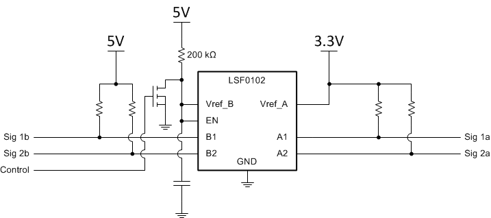
    Instead of driving the EN pin directly, you should add an nFET to ground there as shown here:

  • hello maier

       according your advise,i have change my schematic,however ,now it's work right.

    as you said,there is a pin connected to a controller which powered is 5V,but this issue is not cause by enable pin,

    it's the Vref_B.

    on my schematic ,the Vref_B was connected to 5V power supply ,just like the Vref_A which is connected to 3V3 power supply(i think those poth pins were the power pin),

    when i connect to the Vref_B pin to enable pin,and then these pins pull up by 200k resistor to 5V,the chip work is right,and the chip enable or disable still by 5V controller.

     there is no mosfet. 

    is the mosfet necessery if i want to enable of disable?

    thanks for your help.

  • The enable pin of this device is not a normal enable - it requires an open drain connection, which is what the nFET in the above schematic is creating -- the pin should be allowed to float to the voltage it wants (which should be approximately V_A + 0.85V. Forcing 5V at this pin will cause unpredictable results and possibly damage to the device.
  • hello maier

        thanks for your help,your advise is right,if i connected the enable pin to 5V controller,the  lsf0108 is abnormal again,but  i didn't test it befort i write to you yesterday.

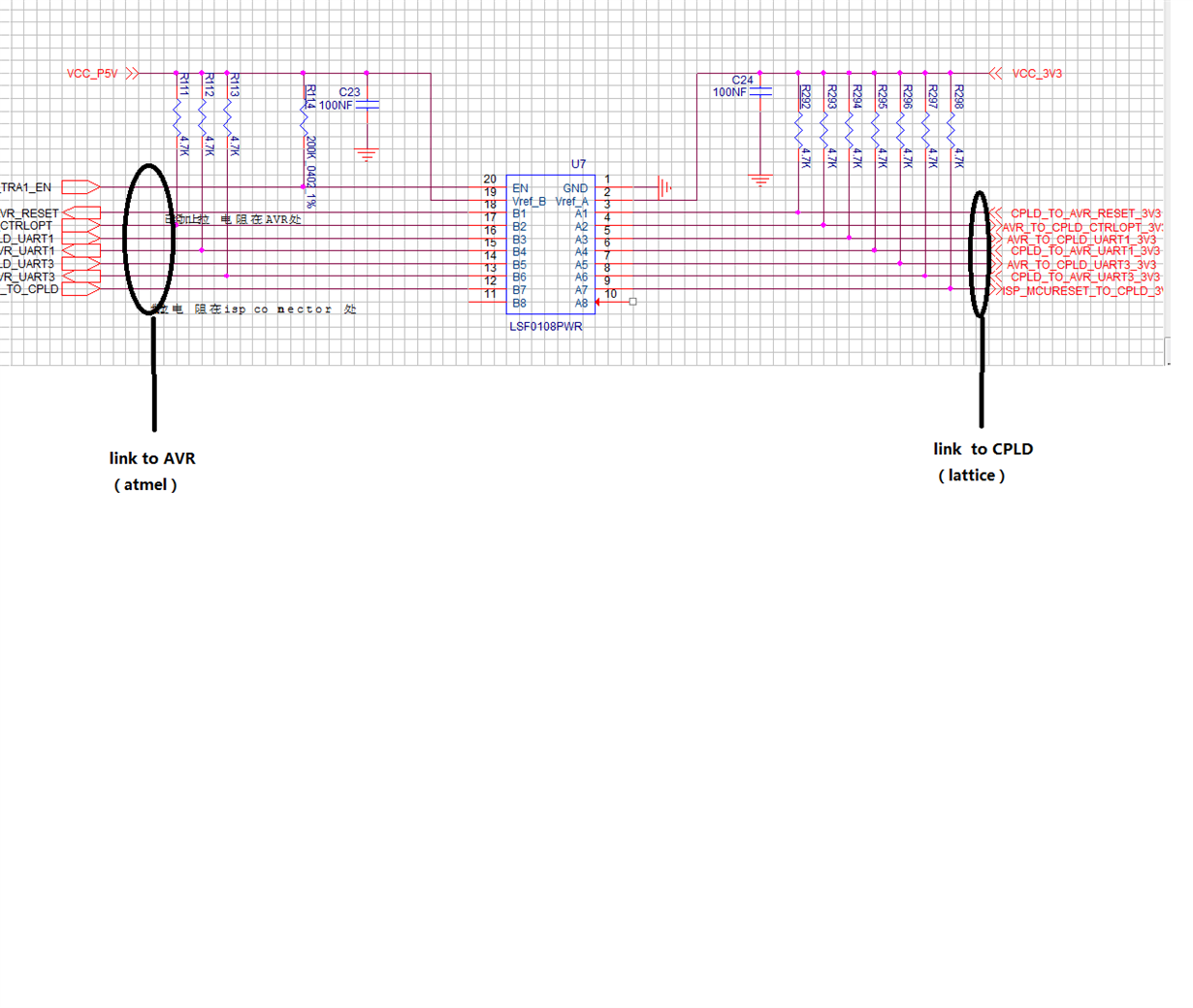
    now i disconnect the enable pin to CPU, the work is ok,and now ,the schematic is :

    enable pin and Vref_B connected together and then pull up to Vcc_5V by 200K resistor(0402,1/16W),just like that, no other connection on those pins(enable and Vref_B),the LSF0108 always enable.

    please double check it for me ,thanks.


  • Hello,

    Yes, this is the correct way to connect the device. The EN and Vref_B should be tied together and tied up to the 5V supply through a 200k resistor, you should not tie the Enable separately to a 5V supply.

    Best,
    Michael