This thread has been locked.

If you have a related question, please click the "Ask a related question" button in the top right corner. The newly created question will be automatically linked to this question.

SN74HC74: How to clock a Flip Flop only when some conditions (decoded by gates) come true.

Part Number: SN74HC74
Other Parts Discussed in Thread: SN74LVC1G17, SN74LVC1G14

In almost any digital design, clocking or resetting a FF (Flip Flop) is almost ALWAYS decided by some logic conditions. For example: a counter must be reset when, say, A=47, and B is true and C is false, OR D is less than 100 and .... etc. In any application, the moment to reset a FF is always determined by some combinational conditions decoded by gates.

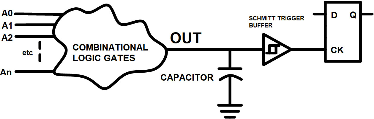
BUT: the output of any set of gates decoding some conditions (like the ones above) may be glitched, may have spurious undesired responses, due to gate delays. 

My question is:

3- How does TI reset a 74HC74 Flip Flop (or an equivalent D FF) according to some conditions like the ones stated above, knowing that decoding this condition with gates will generate glitches/spikes (at the output of the decoder) that could (and will) falsely reset the FF.

2- Similarly, in almost any digital design, clocking a FF (or a whole function like a counter) is determined by some logic conditions decoded by a set of gates. Remembering that decoding with gates could (and will) generate spurious responses and/or glitches, how is it possible to clock a 74HC74 FF from a decoding circuit that could (and will: Murphy's law really works!) be glitched?

If these two questions are not clear enough, please feel free to ask for more details.

Please, tell us the way TI suggests to reset (or clock) a 74HC74 Flip Flop (or equivalent) , in the context above .

  • Hello Serge,

    It is possible that the data path can be longer than the clock period, there will just be additional delay in propagation of the signal to wait for the additional period.

    If there is a glitch being generated from the output of a preceding logic device that cannot be removed and may clock the input of a D flip flop, a capacitor could be added at the output of the device to suppress this glitch. Since there will be additional capacitance on the line to suppress such a glitch, it would be recommended to use a schmitt trigger input device to be able to tolerate any slow edges.

    In this way, the glitch is removed into the schmitt trigger buffer, and it generates a clean fast rising edge input into the CLK of the flip flop which should only clock a single time because of this clean edge. A device such as the SN74LVC1G14 or SN74LVC1G17 would work.
    This should help to avoid any issues due to the glitch.

    Hope this helps!
    Best,
    Michael
  • Hi Michael,

    Thanks for replying.

    1- Let us postpone the path delay vs clock period for the moment.

    2- I would like to make sure that we have both the same understanding of the solution proposed by TI.

    Let us sum-up. In most applications of the real world, it is often required to clock a Flip Flop (FF) or a set of FFs only if some conditions have been detected by a combinational circuit made of logic gates. Such combinatioal gates are prone to spurious response, glitches, spikes, etc. at their output, due to various gate delays within the circuit. Spikes, glitches, spurious response are absolutely normal in combinational circuits.

    Consequently, the output of these combinational circuits may not be used directly to clock a FF, nor to reset it, since transitory responses (glitches, spikes, etc) would falsely clock or reset it.

    The solution proposed by TI would be to add a capacitor to the output of the combinational logic, in order to filter-out its transitory false outputs, and adding a Schmitt trigger buffer to get a nice clock (or reset) signal.See the attached image.

    Have I understood correctly the solution proposed?

    Thanks for your help.

  • Hello Serge,

    Yes, depending on the severity of the glitches/output levels, the capacitor on the output, and maybe a series resistor, could be added to clean up some of these glitches and then when there is a true rising edge, the schmitt trigger will be able to clean up the slow edge to provide a single fast rising edge input to the clock of the flip flop.
    Obviously this solution could limit the maximum operating frequency of the system depending on how fast the desired operation is and what the expected spikes are.

    Do you have a scope shot of your setup that you are concerned with?

    Best,
    Michael
  • Hi Michael, thanks for your proposal.

    The proposed solution introduces a delay on the clocking of the conditionally-clocked functions. (Functions with conditional clocking are activated later than those beeing currently clocked.)

    Suppose the Q output of FF A is connected to the D input of FF B because we want FF B gets the value of FF A when the clock rises. ( positive edge triggered FFs) But we also want FF B be conditionnally clocked : it takes the A value only from time to time. Because the conditional clock to FF B would delayed, an attempt will be made by this FF to register a value that already has disappeared!

    The hard fact is that clocking, conditional or not,  must always be made at the same time in a system, otherwise, some functions, like the simple 2 FFs above, become impossible. Moreover, having multiple clocking times in a system becomes rapidly un-manageable. In my opinion, introducing clocking delays or having multiple clocking times is not a good design practice.

    More generally : A design is typically (if not always) made of a certain number of FFs, whose Q outputs are connected to D inputs of other FFs, either directly (direct Q to D connection) or through some combinationals. These connections could have two modes : feedback and/or feed forward modes.

    Since both modes are allowed, it becomes clear that clocking must be simultaneous everywhere in the system. Introducing clock delays could make many designs impossible : The simple 2 FFs above is a good example showing that delayed clocks do not simply work in such cases.

    Here is another challenge for you:  a system has 2 clean inputs, X and Y. (No glitches on these inputs, fast rise/fall time, etc.) A counter must be clocked when X makes a positive transition and also when Y makes a negative transition. Note that these transitions are random.

    Do you like challenges? A function needs to be clocked from two sources, according to some conditions. As you know, multiplexing clocks is not the right way to go : this would introduce clock delay, (clock skew) which in turn would crash in case of feed forward connections. (Like the 2 FFs above)

    Solutions exist for problems like these, (conditional clocking, resetting, the double transition above, clock source multiplexing, etc) but the solutions involve the design of a new kind of 74HC74 flip flop that is actually manufactured by none of the manufacturers covering this market.

    If you and/or your colleagues find the solutions, please share them with the IC designer staff at TI; they will design new devices that will greatly simplify your customer's life, and could extend the life of the products sold by TI. But if you do not find the solutions, could you put me in connection with the engineering staff who is responsible for the design of new Integrated Circuits? I will discuss with them designing some new products.

    Waiting for your feedback,

    Cheers,

    (I will be out of town for 10 days... vacations.)  

  • Serge,

    We appreciate your inputs, and I can pass them along for review.

    Best,
    Michael
  • Thanks, Michael,

    Waiting for some feedback (no clock delay!)

    Serge

  • Hi Michael, 

    The solution to the problems we discussed is quite simple.

    However, I noticed that none of the discrete logic manufacturers implements it. 

    Why???

    It will simplify the design process using discrete logic,

    It will extend the useful life of these products,

    It will increase robustness and reliability of discrete logic designs,

    etc.

    Please, could you put me in contact with the team responsible for logic ICs development? (Name and email please.)

    Thanks,

  • Hello Serge,

    As I mentioned, this information is shared with our internal team.
    We appreciate your feedback in helping us to think about better ways to design our devices and improve them beyond current designs.
    We always take our customers concerns and ideas into account when thinking about what products we create next.

    While our team internally will review this information, we will not explicitly respond regarding whether or not we intend to implement your specific feedback into any of our designs, as any information regarding our designs and/or our design process is strictly confidential and will not be shared through any form. To that point, while I can respond to your posts through these forums and pass along your information, we will not share specific internal contacts information.

    Again, we always appreciate customer feedback. Thank you for your inputs.

    Best Regards,
    Michael
  • Thanks Michael for replying.

    Your response let me believe that the information has been effectively shared with the appropriate internal team at TI. Note that I have made some corrections and additions to the initial document; should you wish to receive a copy, just let me know.

    Also note that TI is the first manufacturer to be contacted in order to offer the suggested new products to the market. I sincerely believe that the market needs these new products. They will greatly simplify the design process for your customers, and increase the reliability of their products.

    On the other hand, I clearly understand that TI will not share confidential information regarding whether or not she intends to implement my specific feedback into any of her designs. I also understand that this forum is not the right place to have a business discussion.

    However, having made hundreds of logic designs, (Discrete, FPGA, and ASICs) I clearly know that these new devices will be extremely useful for your customers, and I really want to see them offered to the market. For this reason, I will contact, in the next few days, other discrete logic manufacturers to suggest them to manufacture these new products.

    Should TI be interested in increasing her market share, acquiring a competitive advantage for two or three years, increasing her revenues, extending the useful life of the whole logic device family, and more, feel free to contact me with a business proposition. 

    Waiting for a reply before going further, in the next few days, with other manufacturers ,

    Sincerely,

    Serge Mathieu

  • Hello Serge,

    Thank you again for your inputs. We will take them into consideration.

    Best,
    Michael
  • Hi Michael,

    Thanks for your reply.

    Having probably read the initial document, you should now know what I called a -P signal.
    A better name for this signal of a kind would be TIC, a remembrance of the time clock noise,
    or of the sound this signal makes in a loudspeaker.

    We also discussed that the 2 most sensitive inputs to sequential logic
    are the clock and the reset (The latter including set/load). These 2 inputs
    of sequential logic may not be glitched, otherwise false clocking/resetting could happen inappropriately.

    We have also seen that combos generate glitches, and, on the other hand, that combos must be used
    to control the sequential functions in a system, including clocking and resetting.
    We have seen TICs resolve these 2 issues.

    TICs are even more powerful. They can at the same time, with a single signal,
    reset some FFs, activate a state machine, and clock other FFs.
    I sent an example (tachometer) where a single TIC does clock some registers
    while resetting two counters, from a unique event, with a unique signal; A challenge for all 74/4000 designers.
    In fact, it is a challenge for any designer using standard FFs similar to the 74HC74, CD4013, etc.
    These FFs are not well adapted to their task.

    Do you remember the two small challenges we have talked about?
    A) clocking a counter when input X makes a positive transition,
    AND also when input Y makes a negative transition, both inputs beeing randomized? The solution
    is named TICs. One can even easily settle the case where both signals make a simultanous transition.
    An impossible job for 74hc74 like FFs. These FFs alone simply do not do the job.


    No single device Flip Flop offered by TI can take care of this simple task.

    B) We both know that multiplexing clocks is a very bad idea. Multiplexing TICs is fine, providing the desired result.

    A filter needs to be operated at 100 kHz in a 4 MHz system clock environment? TICs.

    May a path delay be longer than the period of the clock applied to FFs ? The answer is Yes!

    Sometimes, a system needs a high frequency clock to process some high throughput data,
    but the rest of the system could process at a much lower frequency, conserving power.
    (Ooops! I am not respecting FSD rules! I am creating 2 system clocks!)

    Easy. Even clock domain crossing in both directions is easy.

    Texas Instruments, with the 74 / 4000 families, offers non-adapted Flip Flops.

    The same difficulties are encountered
    in FPGAs and ASICs, when using similar misadapted FFs. I personnaly designed a few complex ASICs
    using TICs. Design is simplified, TICs are really fun to work with.
    Designers forget the clock. Should a function needs to be clocked, one generates a TIC.

    TICs can now be thought exactly as if they were a clock signal. If FFs are positive-edge-triggered,

    then TICs can be seen as clocks activating FFs on the negative edge of the TIC.

    FSD and ED devices MUST be offered to the market, on all support available, including 74/4000 devices.


    Just like all other discrete logic devices manufacturers,

    Texas Instruments  does not offer at this time, in her 74 / 4000 products,  the required FFs for the job.
    TI must offer the products I have suggested, simply because the market needs these products.

    FSD and ED products MUST be offered to the market. Texas Instruments  MUST offer better designed FFs,

    because the actual standard devices made by all discrete devices manufacturer are not well adapted to the job.

    The proof of this affirmation is the following:  in a real application like the tachometer mentioned earlier, 

    try to use a single and glitched signal to elegantly reset one FF while clocking another, using the actual FFs offered by Texas Instruments. 
    A difficult task for such a simple problem. 

    I also understand that some education will have to be done in parallel with the introduction of these products. I have found no application notes
    in Texas Instruments documentation, on how to fully exploit the power of the 74HC163, one of the sole function in
    this family capable of using TICs.

    There is much more to the "count-enable" input of this device than just expanding the function to 8 bit!

    Unfortunately, this device has no asynchronous reset to use at power-on,
    making it more difficult to design with. The same for some registers like the 74HC377; It could use TICs:
    unfortunately it has no power-on reset, so that this device could exhibit random values at power-on,
    impeding its use in many applications.

    The need really exists in real life: 

    a single event must be capable of simultaneously activating the sequential functions, clocking one while resetting the other!

    -------------------------------------- 

    To conclude, once again:

    It is my profound conviction that the devices I suggested that Texas Instruments manufacture are needed in the market.
    Any designer having seriously analyzed my suggestions will conclude that these products
    must be manufactured by at least one discrete logic manufacturer.

    As said, I will contact other logic devices manufacturers, because I am intimately convinced that the products
    I suggested will make a difference for your customers. I will wait 10-15 days before doing so.

    Thanks for your support, 

    Serge Mathieu
    smathieu13@hotmail.com

  • Serge,

    Thank you again, your inputs are appreciated.
    Best,
    Michael
  • Hi Michael,

    sorry to bother you, I wanted not to come back again, but I need to be absolutely sure

    that Texas Instruments has in hand the small document describing succinctly the devices I suggest that TI manufactures. 

    This document is the basis of all our discussions. This document should be analysed by the appropriate staff at TI,

    along with our own discussions that complete the whole picture, including the post where I say that all discrete FFs

    actually on the market are not the appropriate ones, because, with these existing FFs, no single glitched signal can reliably, simply,

    from the same signal, and at the same time:

    reset some FFs, AND clock some others, which is a real necessity in real life. TICs can do it.

    I have made a few additions and corrections to this document you should have in hand, but the essentials are the same. If you want an up-to-date copy, just ask!

    So please, would you confirm me that 1) Texas Instruments has the document "SyncDesign2 or 3" in hand, and 2) analyses the proposed new products. 

    After this confirmation, I will no more bother you with this subject, having done all I can do to convince Texas Instruments

    to manufacture these new, better adapted, easier to use, lower part count, more reliable, etc.  products. 

    Thanks again, I hope we will meet someday. 

    Sincerely,

    Serge Mathieu

    smathieu13@hotmail.com