Hi team,
The customer is using CD74HC93. He uses the a 4-bit ripple counter. The Q0 pin is connected to CP1 pin.
The input channel is CP0 pin. VCC is 5V. The schematic is in the attachment.
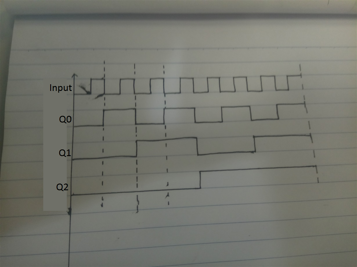
Now the customer would like to verify the TRUTH TABLE of the datasheet. According to the TRUTH TABLE, I have drawn the Q0~Q3 waveform.
Please check the attachment. But I do not know the relationship between the input pulse signal waveform and the Q0~Q3 output waveform.
Would you please send me the input pulse signal waveform? Then I will know the output signal start to reverse in Rising edge or falling edge
of the input pulse signal.
What is the frequency range for the input pulse signal ?
Best Wishes,
Mickey Zhang
Asia Customer Support Center
Texas Instruments


