This thread has been locked.

If you have a related question, please click the "Ask a related question" button in the top right corner. The newly created question will be automatically linked to this question.

TXB0108: ESD fail +-2KV

Part Number: TXB0108
Other Parts Discussed in Thread: STRIKE, TPD4E1U06

i am using a wifi device with TXB0108. The entire product failed at the time of compliance test. we check all the components . For this level Shifter has +-15 KV in the datasheet . we changeed all other componet expect this . every time the device failed in ESD test. at last we changed this transalator . then we tested .. miraclely the device passed the test. i am a new one in ESD measurement .. is ti gave wrong information in datasheet?? 

  • Hi Angel,
    I have notified the appropriate applications engineer who will be back with you soon.
  • Angel,

    The discrepancy is that the TXB0108 is rated for 15kV HBM ESD strike. This uses a 100pF capacitor and 1500 Ohm resistor.  Please check the value of your ESD gun and make sure that is what you are testing with.

    The HBM is different than the IEC61000-4-2 ESD strike which uses 150pF 150ohm or 150pF 300 ohm. This pulse is much more strenuous to the device and will probably require external protection devices.

    Regards,

    Cameron

  • Can you suggest me some ESD protection ckt for this Chip?

  • Hey Angel,

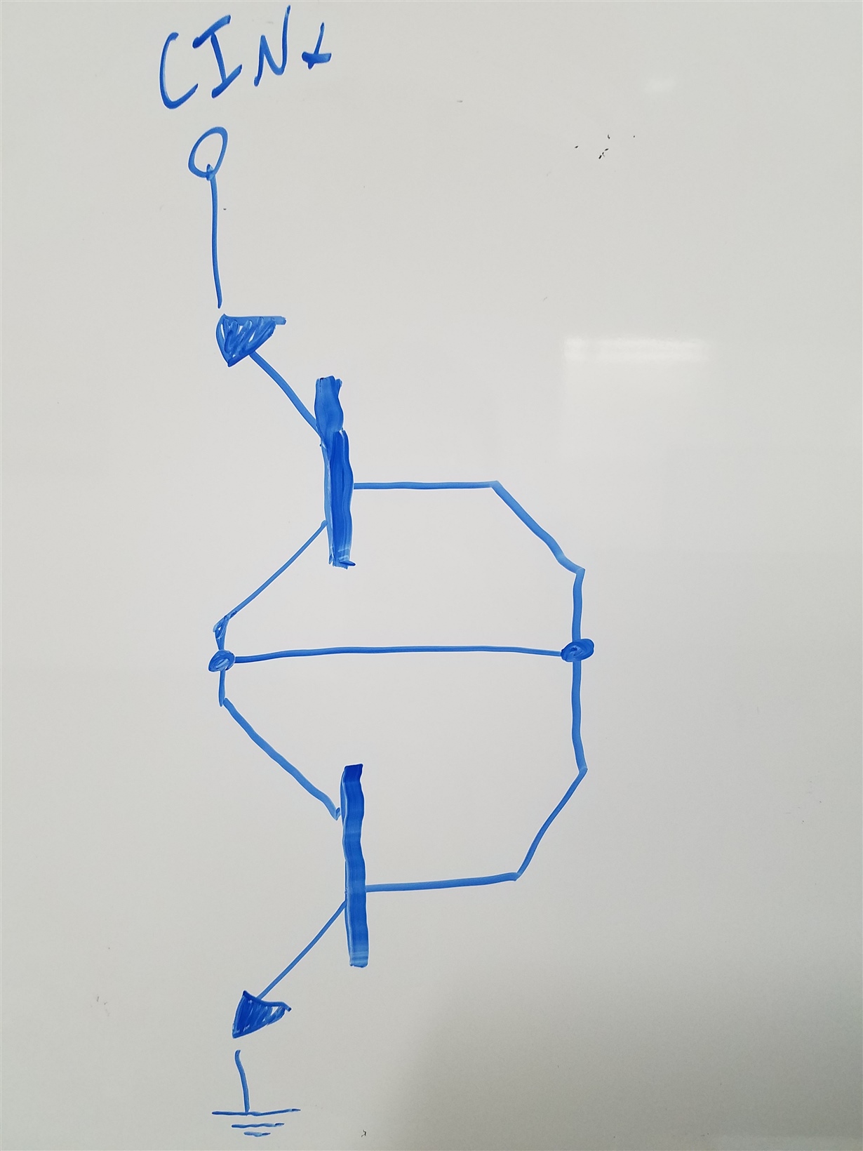
    I'm sure cameron will have a good solution for you in a bit when he sees this. I myself am partial to using  a Bidirectional BJT Zener Clamp for inputs and the like. It has very fast response times and very low capacitance. The trade off is more parts and finding a BJT that will fit your needs but once you do it works well. I've attached a circuit schematic below that has two NPN BJTs since it is hard to find the circuit I'm talking about since most don't use it. Fluke uses this circuit on the input of most of their meters though! I'm not sure how well it works for sustained high voltage events but for transients it should work well.

    Pardon the "CINx", it was from a different problem. You can attach this circuit between any two potential but typically it's across Vin and GND.

    If this answered your question please verify the solution with the green button below! If not, feel free to forward along any additional questions to me.

    Best Regards,

    Nick

  • How is this circuit working ??
  • Angel,


    The way this is working is you are basically making two diodes one facing one way and the other is facing the opposite. This means when the you reach the breakdown voltage of the first diode  plus the forward voltage of the second, current will begin to flow through to ground, effectively protecting any down stream devices that are not rated for this much power. The IEC 61000-4-2 is very quick but has a large amount of energy. If you can direct that energy to go through the protection device instead of the IC your other devices like the level shifter will be protected.

    However, using the two PNP like Nicholas said will require using two BJTs that you know all of the specifications to and will have very large area. If you want something simple to use, you can use two TPD4E1U06 since they are four channel devices and you will pass IEC 61000-4-2 up to +/-15kV

    Regards,

    Cameron

  • Cameron has nailed it on the head, the protection voltage is the combination of Vebo (emitter base voltage maximum) and a diode drop. One of the many models of a transistor is two zener diodes back to back with both in a forward biased configuration from B to C and B to E with B being shared between both. When the voltage is sufficiently high to meet the Vebo + 0.6V voltage, the circuit conducts and the circuit will shunt to GND. 

    I looked at the device that Cameron recommended and it also operates off of diodes in a similar fashion. The data lines will be forward biased and conduct through the diodes in normal operation but when an over voltage fault is detected it will bias the zener, allowing it to conduct. This will shunt excess current through the ESD protection device and not into your downstream device. See inserted block diagram of TPD4E1U06 part below:

    This one chip solution will probably be best for you since it is small, and is spec'd to meed the tests you will be running on it. On the bright side, you learned of a new BJT circuit, always a good day!

    If this answered your question please verify the solution with the green button below! If not then feel free to send additional questions my way and I will answer them as soon as I can for you.

    Best Regards, 

    Nick

  • Thank you Cameron. at present application will i use two transistors?? is one transistor enough??
  • Hey Angel,

    I think you might have some confusion, our recommendation is that you don't use the Bidirectional BJT Zener Clamp circuit, but do use the TPD4E1U06. Both of these solutions are viable but the TPD4E1U06 will have a smaller footprint, is spec'd to work at IEC 61000-4-2, and will be easier than having to spec a transistor. Following Cameron's instructions below will solve your problem in a neat and tidy way:

    "If you want something simple to use, you can use two TPD4E1U06 since they are four channel devices and you will pass IEC 61000-4-2 up to +/-15kV" - Cameron

    If this answers your question please verify the solution below by hitting the green button! If you have additional questions just send them along and I'll be happy to answer them as soon as possible for you.

    Best Regards,

    Nick