This thread has been locked.

If you have a related question, please click the "Ask a related question" button in the top right corner. The newly created question will be automatically linked to this question.

SN74LVC2G14: Application for UART with a 3 meter cable

Part Number: SN74LVC2G14
Other Parts Discussed in Thread: SN74LVC2G04, SN74LVC1G3157

Hi,

My customer is using SN74LVC2G14 for an application with topology as below.  The 3 meter cable is connected between two systems.

  TMC module output UART TX--> Inverter (SN74LVC2G14) --> Connector  --> 3 meter cable  --> Connector --> switch  (SN74LVC1G3157DCKR) --> SOC UART Port

They need this inverter here because the TMC unit UART is an invert of standard UART. 

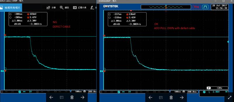
With such implementation, the SOC UART Port can't detect the UART signal (19.2KHz) correctly, even though the UART waveform signal looks ok (before and after the 3 meter cable.)  But, if they add a 10kohm resistor to GND at the output of SN74LVC2G14, the test result becomes ok.

So, the questions would be

  1. Do you see any concern for such implementation?  Do they need a UART buffer to enhance the driving strength for the 3-meter cable?
  2. From above, which IC would we propose for this buffer?
  3. How can we explain the 10kohm resistor is helpful here?

Thanks!

Antony

  • Hi Antony,

    It's likely that the 3m cable is introducing some transmission line characteristics into the system, which typically produces a large amount of overshoot/undershoot at the distant end due to impedance mismatch (50Ω cable into high impedance CMOS input).

    By reducing the termination impedance to 10kΩ, the impedance match is improved and the ringing is reduced. If it is reduced enough for the system to operate properly, then I would say to go ahead with that design.  There is a useful document that discusses this in detail: Design Considerations for Logic Products

    SN74LVC2G14 or SN74LVC2G04 would be viable options for the inverter. There are also many other options depending on the required voltage - a 19.2kHz signal is no problem for any logic inverter (typically they can run into the MHz.

  • Hi Emrys,

    Thanks for your reply.  We have some discusiion here and not sure about some of the points you mentioned.

    1. Regarding "50ohm", do you assume the cable is usually implemented as 50ohm impedance?
    2. Regarding "high impedace CMOS input", does it mean SN74LVC1G3157DCKR has a high impedace CMOS input?
    3. Do you mean a possbile solution is to increase the imdance of cable/connector to 10kohm so that it can match SN74LVC1G3157DCKR input?  IF this is true, what can customer do to achieve this?

    Thanks

    Antony

  • 1. Yes, I assumed 50Ω impedance on the cable since that is a very common characteristic impedance for transmission lines - your cable could be higher or lower, but it would result in the same issues.

    2. It depends on which input of the SN74LVC1G3157DCKR you are talking about -- the control input is a standard CMOS input, while the analog switch will either be high impedance or a short to the other side. Since I don't have a schematic or know how your system works, I have to assume that the logic signal will be going to a logic input at some point.

    3. No, the cable impedance is set. The 'termination impedance' is just a resistor to ground at the distant end of the cable (which you said they already have, or did I misunderstand?). The link I gave goes into details on why this is helpful.
  • Hi Emrys,

    THanks for your reply.

    Regarding the 'termination impedance' at the distant end of the cable, do you mean they need to placed close to the input of SN74LVC1G3157DCKR, or close to output of SN74LVC2G14?  Currently they implement the 10kohm close to output of SN74LVC2G14.  Would this be helpful?  (They may not be able to change the design on the board with SN74LVC1G3157DCKR.)

    THanks!

    Antony

  • I would think that placing at the distant end (the input to the SN74LVC1G3157 in this case) would be best.
  • Hi Emrys.

    Customer try to place the 10kohm to GND at the input of SN74LVC1G3157 and it works.  SOme questions from customer as below,

    1. How can we judge if 10kohm is the best value for it?
    2. Customer didn't finsd waveform difference before/after adding 10kohm at the input of SN74LVC1G3157 (as shown below.)  Do you have any comments?

    Antony

  • It looks like there is a reflection in the line causing a slight spike at about Vcc/2 - which can be problematic since that is the threshold voltage for most CMOS inputs. I would say that the best fix would be to add a Schmitt-trigger buffer at the distant end of the cable (prior to the SN74LVC1G3157).  This will eliminate any chance of the reflection causing a double trigger.

    As for why they see an improvement - note that the 10k resistor reduces the reflection slightly, as shown here:

    That reduction is likely just enough to avoid a double trigger in their current setup - I would not trust it to _always_ be fixed, however, due to variations from device to device.

    If the only option is to add a terminating resistor, lower values will be better to reduce the reflection. The closer you get to the cable's characteristic impedance, the better - however, you cannot exceed the current driving capabilities of the driver device and if you have a perfect match, the signal's value will be cut in half and it won't be recognized at the distant end.

    A better solution is to add a series resistor at the output (prior to the cable), which will dampen oscillations.

    Yet another option would be to increase the cable length slightly (perhaps 1/8 to 1/4 wavelength) - by changing the length of the cable, you can change when the reflection hits the edge, and move it outside of the switching threshold range of the device you are communicating to.

  • Hi Emrys,

    hanks for your comments.  Regarding your comment of "If the only option is to add a terminating resistor, lower values will be better to reduce the reflection. The closer you get to the cable's characteristic impedance, the better - however, you cannot exceed the current driving capabilities of the driver device and if you have a perfect match, the signal's value will be cut in half and it won't be recognized at the distant end", is there any material describing the mechanism to adjust the resistor value?

    Customer have some test result as attached as a reference.

    Thanks!

    Antony

    waveform check.xlsx

  • The reflection coefficient (p) can be calculated with:

    p = (Zterm - ZO)/(Zterm + ZO)

    If we assume that the transmission line is 50Ω and the termination is perfectly resistive and has a termination of 10kΩ, then the reflection coefficient will be:

    p = (10000 - 50) / (10000 + 50) ~= 0.99

    To compare to the device without a termination resistor, we can assume the input is around 3.3 MΩ (3.3V / 1uA):

    p = (3300000 - 50) / (3300000 + 50) ~= 0.9999

    That means the 10kΩ resistor only improved the reflections by about 1% (from 99.99% to 99%) 

    If you match the impedances perfectly, the reflection coefficient drops to zero (the ideal case), however that adds a lot of new problems (current drive, voltage drop).  The driver is strong enough to handle a 1kΩ load (3.3V/1kΩ = 3.3mA), which produces a reflection coefficient of ~0.9.  This is 10x the reduction that the 10kΩ resistor provided (going from 99.99% to 90%).

    I found a calculator online where you can get this value quickly and easily:

    ncalculators.com/.../transmission-line-reflection-coefficient-calculator.htm