Part Number: LSF0108
I have a customer who is asking the following questions (customer responses in BLUE, my responses in BLACK):
When using the lsf0108.ibs model, how should I select the Series_switch model? I am translating between 1.8V (VREFA) and 3.3V (VREFB). What's the correct reference voltage for Series_switch?
I told the customer that she should use the 3.3V model? Is this correct?
How about when it is translating down? Do I need to change the switch model or keep the 3.3V model?
I did not believe that it would make a difference, but the results are shown below.
Also do I need to flip the series pin mapping if the signal direction is from B to A? … are there any length restrictions for this part? One side of the lsf0108 part is about 8” from the driver/receiver part and the signal is going through two connectors. Could the lsf0108 part be able to work with the traces that long?
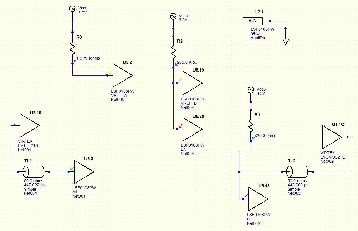
For test purpose, I took out the connector models and placed 50ohm traces, about 8.0” on one side and 1.5”on the other.
This is how it’s setup. I was using 402ohms on 1.8V side and 750ohm on 3.3V side, but it wasn’t enough to clear the thresholds so it was increased to 150/300ohm for 1.8V to 3.3V direction. We want to run this at 25MHz for now.
Here is a picture of their simulation:

This is what I see… from 1.8V to 3.3V: blue (slow) and red (fast). At slow corner case, it’s not clearing the input threshold…, pullup values are a bit strong but within the recommended range. At typical it barely makes it to 2.0V.

From 3.3V to 1.8V: it doesn’t go low enough for slow (blue) corner case, it stays at ~2.3V….
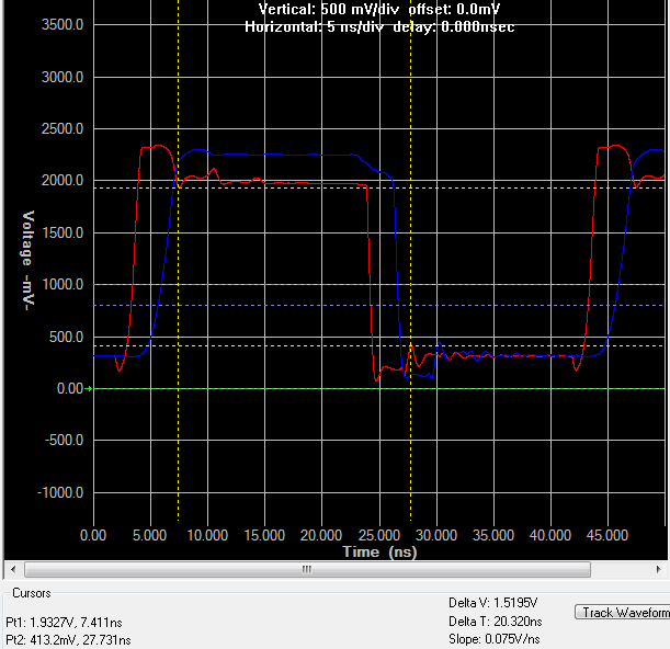
Should the customer be changing the model when translating down? Shouldn’t the model work either way?
Can you test this and let me know if you get similar results?
Thanks for your help with this!
Richard Elmquist