This thread has been locked.

If you have a related question, please click the "Ask a related question" button in the top right corner. The newly created question will be automatically linked to this question.

TXB0108: Issue when measuring the B side of the component

Part Number: TXB0108
Other Parts Discussed in Thread: SN74HC245, SN74HC244, SN74CBT6800A

Hello,


I am currently using a TXB0108 in one of my design. The schematic of the board is the following:
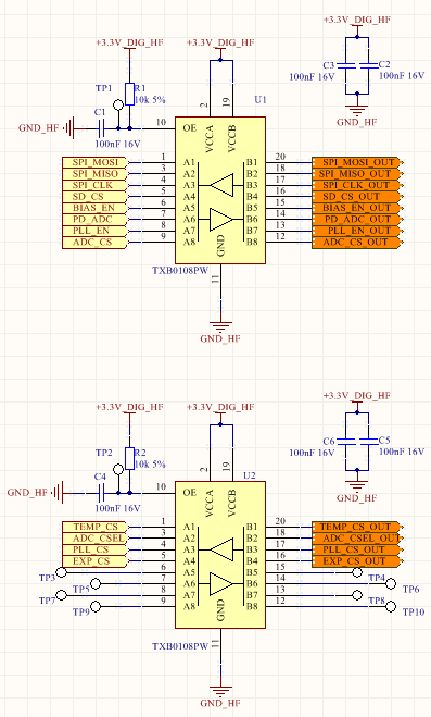
Full board:

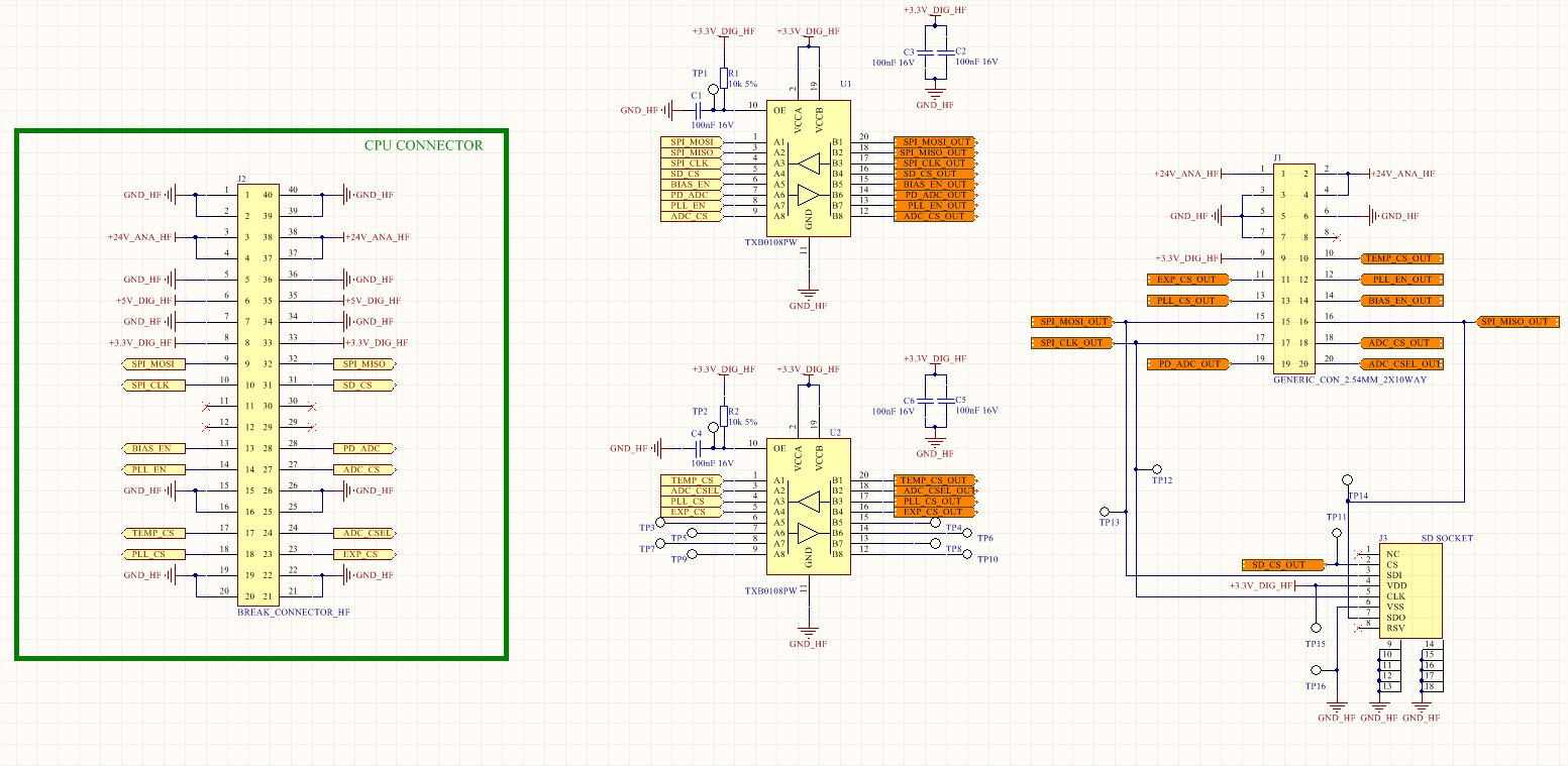
The purpose of the TXB0108 is to protect the CPU board (J2) from the board connected on the J1 connector. There is a risk of hot insertion on J1 that will cause a current sink from CPU to daughter board. I have damaged two CPU with this and to avoid this problem I have decided to add a voltage isolator to protect the CPU I/O lines. 

So, the TXB0108 will use the same power source for both Vcca and Vccb.


When I watch the SPI CLK signal from the CPU with my scope I got this:

If I measure the same signal after the TXB0108 I got this:

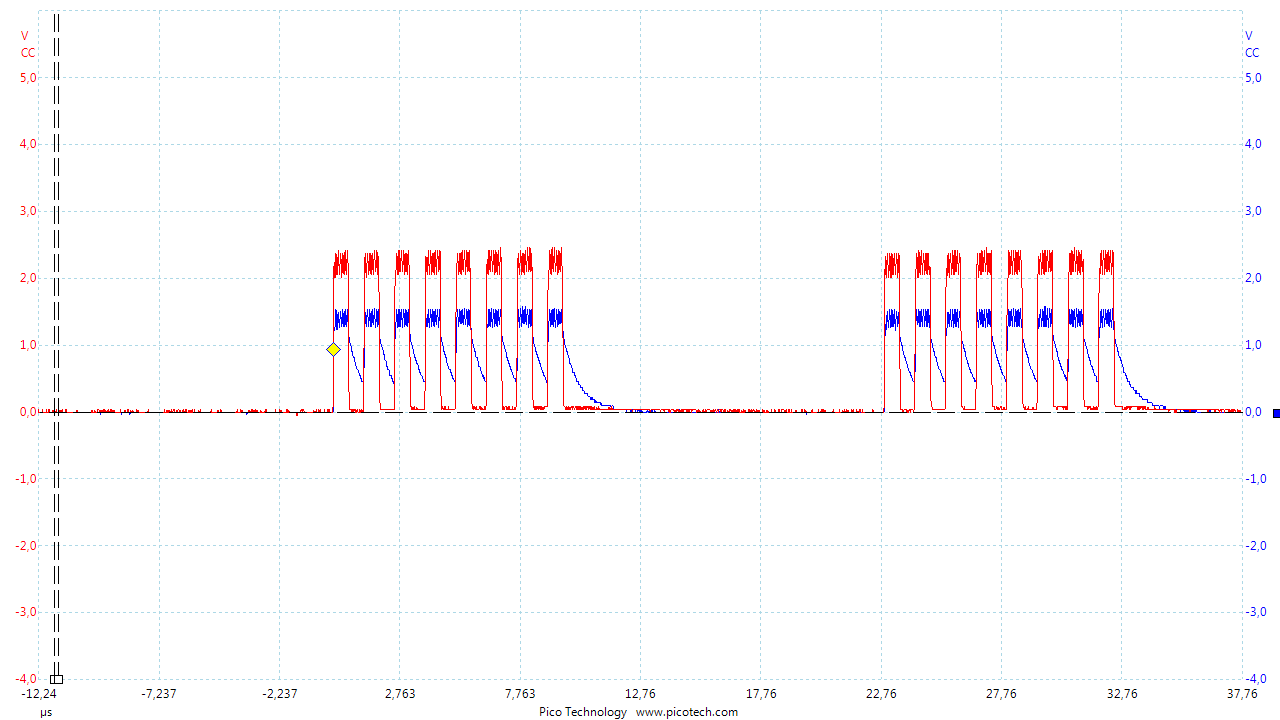
Both signals are now bad. The output of the CPU has a big amplitude loss. The output is 1.5V max.


I use a Picoscope 2204A. The input impedance is 1M/14pF. I think the scope is a part of the problem, maybe I shouldn't use this component for with the same power source? 

I have order a TXS0108 to see if the behavior is better.

Is there someone who can help me?

Thanks' a lot.

  • Hi,
    The schematic shown is missing a lot of details - I don't know what our device is connected to or from. The TXB device can't drive much current (~20uA max), so it's likely that your circuit is trying to drive more current than the device can handle.

    It looks like you want to have a 3.3V input and a 3.3V output and all your signals appear to be unidirectional - why not use a transceiver like SN74HC245 or a buffer like SN74HC244?

    Can you share a full schematic or at least a block diagram to show what you are trying to accomplish?
  • Thanks' a lot for the fast answear. I have cut the image of the schematic to avoid a too big image in the tread. I will post the complete schematic of the card. So, sorry for the incovenience with the big image.

    On the yellow label there is the signals that come from the CPU (Microchip PIC32MX) on another card. The Orange label are the output of the card to the daughter board. There is an SPI communication and a few CS signals.

    Note: the scopes posted in the original post has been made without device connected to the B side of the TXB component. So the only leakage of current should be in the scope?

  • To put the answer up front: I'd recommend using a device designed for hot-swap isolation, such as the SN74CBT6800A.  There's a great application report written about hot-swap protection, called "Bus FET Switch Solutions for Live Insertion Applications." My group doesn't directly handle those devices, so I would have to ask an apps specialist from their team to comment if you need help finding the right device in that portfolio.

    There's definitely something pulling the CPU line down -- how much current can the CPU drive? It needs at least 3mA to overpower the TXB and switch the input - it looks like it's struggling there, which might mean that the TXB output on the CPU side is still driving low. With the 4kohm internal resistance, the current sourcing from the CPU would only be ~350uA. That's probably why the other side is low, too. CMOS devices typically need the input driven much closer to Vcc to get a clean output.


    It's also possible that the TXB was damaged ina  similar fashion to what happened to the CPU in the first place - it's not designed as a protection device.  I'd replace it with a switch designed for that purpose.

  • Thanks for the advice Emrys,

    I think I will go for a switch rather than a voltage isolator. I have take a look at the report and it fit what I want to do.
    So, I will dig in that way. Maybe I will post something in the switch & multiplexer section.

    To respond at your questions: the CPU can drive 35mA, it should be enough to drive the TXB. As you say the CPU side seem to be driven low. Maybe the action to put the scope probe on the output stimulate the component to change way. It could explain why the CPU signal act that way.

    The TXB is not damaged, I haven't try to hot plug something on it. I have the same issue on the both card I have build.


    Thanks a lot.