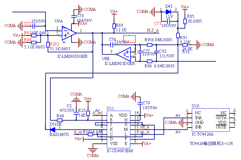
Hi team,
The customer is using CD4093B. On his boards, many CD4093B devices are hot serious. And the supply voltage of
CS4093B is pulled low. The customer's schematic is in the attach. VA+ is 15V.
Q1: Can D pin, H pin and E pin be connected to VA+ directly?
Need to add the current limiting resistor in these pins? If they are needed, what is the current limiting resistor value?
What is the current range for the input pin?
Q2: The customer needs to use the output signal of J pin as the input signal for G pin and F pin.
He also needs to use the output signal of L pin as the input signal for C pin, like his schematic. Is this OK?
Would you check if the customer's schematic is correct?
Q3: What is the input voltage range? From VN to VDD?
Would you explain what are the VP and VN?
Best Wishes,
Mickey Zhang
Asia Customer Support Center
Texas Instruments


