This thread has been locked.

If you have a related question, please click the "Ask a related question" button in the top right corner. The newly created question will be automatically linked to this question.

TXS0104E: OE pull down resistor value

Part Number: TXS0104E

Hi, 

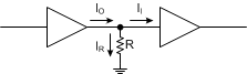
In TXS0104E datasheet, we mentioned " The minimum value of the pulldown resistor to ground is determined by the current-sourcing capability of the driver."  I don't fully understand this.  Can you provide more explanation with an example?

Thanks!

Antony

  • If, for example, VCC is 5 V, and the resistor, 1 kΩ, then whatever device pulls the line up must be able to source 5 V / 1 kΩ = 5 mA.
    In other words, the minimum resistance is VCC / Imax.

    In practice, low-valued resistors waste more power, so they are used only when you need to switch at a high frequency.
  • Hi Antony,

    The OE pin of the TXS0104E is a high-impedance CMOS input. As such, we can model it as a simple buffer for my example.

    In the above image, the left buffer represents the 'driver' device, and the right buffer represents the input to the TXS0104E.

    Note that I_I is the leakage current of the input pin, which is specified as less than 2μA in the datasheet (and can be positive or negative). In most circumstances, this current can be ignored (most drivers operate in the mA range).

    So, how do we determine the output current of the driver?  Ohm's law: V = I * R

    The driver will attempt to drive the line to Vcc, for my example let's call it 3.3V. If the driver has a maximum output current of 3.3mA, then we can easily determine the smallest value of R that can be supported:

    R = V / I = 3.3V / 3.3mA = 1kΩ

    If the resistor is larger than 1kΩ, say we make it 10kΩ:

    I = V / R = 3.3V / 10kΩ = 330μA (which is less than our fictitious driver's maximum current output)

    And if we make the resistor smaller, say 330Ω:

    I = V / R = 3.3V / 330Ω = 10mA (which is larger than our driver's max current output)

  • Hi Emrys,

    Thanks for your comments.  I just check your comments again, and found something that I dpn't understand well.

    On customer board, do they need to pull-up OE pin to Vcca power rail or they just nee to have a pull down resistor GND?

    I see from datasheet  there's only pull down resistor on OE, does it expect the system controller to drive OE pin to 1.8V?

    From tidrh34.pdf as shown below, it directly connect OE pin to VCCA domain.  Then we don't need a pull down resistor on OE pin?  Should we always use 10kohm for this scenario?

    Thanks!

    Antony

  • Your question depends on the customer's requirements. If they want the TXS0104E to be disabled during power-on, then the resistor should be pulled down to ground. If they don't care about the state of the TXS0104E (which is very common), the OE pin can be connected to Vcc. There is no need for a series resistor in this scenario, as the OE pin is a high impedance input and will not draw current.
  • Hi Emrys,

    Thanks for your comments. For the case if they the want to keep TXS0104E disabled during power-on with pull-down resistor to GND implemented, they also need to connect it to Vcca power rail directly, right? And the pull-down resistor value depends on the Vcca's maximum current capability, right?

    Thanks!

    Antony
  • If they want the device disabled at startup, then it cannot be connected directly to Vcca. The pin must be held LOW during startup to remain in high impedance, then a signal would be required to force the OE pin HIGH to start operating.
  • Hi Emrys,

    Thanks! Considering OE is connected to Vcca only, what would be the B side I/O status when Vccb is valid but Vcca is not valid (0V)? Would B side I/O be high impedance at this moment?

    Thanks!

    Antony
  • When either supply is at 0V, the device is in partial-power down mode and all I/O will be high impedance.