This thread has been locked.

If you have a related question, please click the "Ask a related question" button in the top right corner. The newly created question will be automatically linked to this question.

TXS0108E: Question about VIH/VIL range

Part Number: TXS0108E
Other Parts Discussed in Thread: WL1837, WL1837MOD

Hi, team,

My customer has some questions about TXS0108E VIH and VIL may need your confrmation.

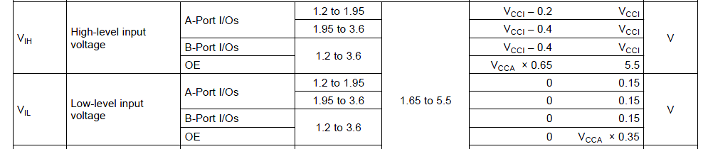
In TXS0108E datasheet, when setting A-port power voltage to 1.8V, VIH range is 1.6~1.8V, VIL range is 0~0.15V.

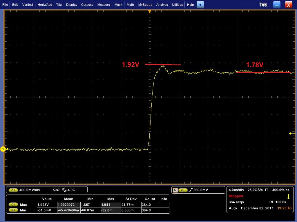
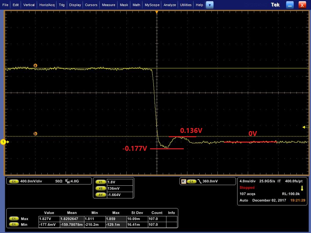
In customer's test, the A-port signal voltage is as below.

For LOW-HIGH, the overshoot is 1.92V, the static is 1.78V.

For HIGH-LOW, the negative undershoot is -0.177V, and the first ringing peak is 0.136V.

My questins are as below.

1. Is it okay for TXS0108E with above A-port input signal waveform LOW-HIGH and HIGH-LOW?

2. Is the VIH/VIL range so strictly small? For example, customer uses NXP LS1043A at TXS0108E A-port input side, the spec of LS1043A is VOH MIN=1.35 V, VOL MAX=0.4 V. How is the risk to use TXS0108E here with LS1043A ?

Thanks.

Johnny

  • 1. Those over/undershoots are harmless. As shown in the absolute maximum ratings, they must not exceed 0.5 V (if the current is larger than 50 mA).

    2. The recommended operating conditions ensure that the device behaves as specified in the electrical characteristics.

    The TXS uses passive switches; when on, they behave like a small resistor. This means that the switches have a voltage drop over them, and to ensure that the output voltage stays below VOL, the input voltage must be even smaller.

    If your circuit does not need the specified VOL, you can use a higher VIL.
    If your circuit does not use the specified current, you get a smaller voltage drop, and you get the same VOL even with a higher VIL.
  • Clemens,

    Thanks for your reply.
    I still cannot understand the comments on point 2. Since LS1043A VOH MIN=1.35 V, TXS0108E VIH MIN=1.6V, How to ensure the signal pass correctly here?
    And if LS1043A VOL MAX=0.4 V, TXS0108E VIL MAX=0.15V, how to ensure the signal passes correctly?

    Thanks.
    Johnny
  • Hi Johnny,

    The TXS0108E does need the input voltage to be at least 1.6V to reliably detect a 'HIGH' input.

    I'm certainly no expert on NXP's parts, but the LS1043A datasheet lists VOH as 1.35V minimum with IOH as 0.5mA (about a 900 Ω driver).

    When the LS1043A is attempting to drive the line HIGH, is there anything else on the line holding it low? Ie, is there a current draw of 0.5mA on the driver?

    If not, then this should work fine. The only thing (typically) pulling the line low when the driver is switched would be the leakage current, which is on the order of 1uA. Even a weak driver should have no problem pulling the line up very close to 1.8V.

    What I would be more concerned about on that device is the output LOW voltage. Since the TXS0108E has 10kΩ reistors on each input, the driver will have to sink approximately (assuming 1.8V to 3.3V operation):

    (1.8V - 0.4V)/10kΩ + (3.3V - 0.4V)/10kΩ = 0.43mA. (getting close to their listed 0.5mA spec)

    As long as those are the only pull-ups on the line, it should work fine - but if anything else is adding current (ie the driver has to sink more than the 0.5mA spec), you might see the VOL drift up to unacceptable levels.

  • Emrys,

    Thanks for reply.

    1. So the internal RPUA and RPUB are all 10k pull-up resistor?

    2. If we pull-up A1 or B1 pin through extra pull-up resistor, for example 4.7k, the LOW voltage will be a bit higher than normal. Am I right?

    3. What is the ON resistor of internal Switch?

    Thanks.

    Johnny

  • Hi Johnny,

    To answer your questions one by one:


    1. So the internal RPUA and RPUB are all 10k pull-up resistor?

    No, I mistakenly used a value from a different TXS device of 10 kΩ. The datasheet lists the correct value (40 kΩ) just below the image you posted:

    So, my calculations are off by a factor of 4 -- the current is one fourth of my original estimation.


    2. If we pull-up A1 or B1 pin through extra pull-up resistor, for example 4.7k, the LOW voltage will be a bit higher than normal. Am I right?

    Yes, the driver will have to sink extra current due to the overall reduction in pull-up resistance, and sinking more current means it will have a higher VOL.


    3. What is the ON resistor of internal Switch?

    This is in the datasheet, also just below the image you posted:

  • Hello,

    I have a similar question, and since I saw numerous posts about this part's threshold voltage levels, I figured I could tag onto an existing one.

    I have the same concern as the person who posted this forum:

    e2e.ti.com/.../635870

    That post is locked, so I can't reply to it.

    I'm using the TXS0108E to translate from 3.3V to 1.8V, and seeing the ridiculously tight VIH and VIL requirements to guarantee proper logic level detection, I don't see how this component can be usable in a typical voltage level situation. I am especially concerned because the TI DM388 Camera Starter Kit design, which I am referencing for my project, uses the exact same translator in the exact same way that I am using it: to communicate with the DM388 processor and the TI WL1837 WiFi module. Looking at the spec sheets for the DM388 and WiFi module, the logic level voltage thresholds are not compatible with the TXS0108E, even though it is used in the reference design. There are no additional pullups/pulldowns in the schematic on these lines.

    Can someone from TI guarantee that the logic thresholds will all work all of the time as is designed in the TI CSK, or confirm that the TI CSK design is using a non-compatible voltage translator.

    Thanks
  • Your question is already answered in this thread.

    In short: the TXS's VIH/VIL requirements are to reach the VOL/VOH specifications for a current that is higher than the one actually used in the DM388/WL1837MOD circuit.

  • Hi Clemens,

    Thanks for the response. I just want to make sure that I understand correctly. The "accepted" response says that the the TXS0108E does need the input voltage to be at least 1.6V to reliably detect a 'HIGH' input.

    This means that it is up to the component acting as the driver (VOH/VOL) to make sure that it has sufficient drive strength to maintain a 1.6V minimum output on the translator's input line. The WL1837MOD VOH spec, says that it can drive a High voltage of (1.8V-0.45V) with a current of 4 mA, essentially meaning a source impedance of 337.5 ohms. As long as the input impedance in the TXS is high enough to limit the source current sufficiently, then the WL1837 can obtain the 1.6V requirement. How can I determine what the input impedance is of the TXS?

    Thanks,
    Gabe
  • The TXS does not have an input impedance because it does not have inputs; each channel is a passive switch.

    When neither side is pulled low, the FET is off. In the worst case. the leakage current is less than 20 µA, so with the output impedance of 0.45 V / 4 mA = 112.5 Ω, the voltage drop is less than 2 mV.

  • Thanks for the clarification. I think I understand now.

    When A1/B1 is high, the internal FET is off and the internal pullups bring up the voltage to its respective VCC level. When A1/B1 is low, the internal one-shot causes the FET to turn on and thus passing through the logic low to the destination chip. As long as the signal traces aren't too long, the TXS should have no trouble driving the required logic levels to communicate properly with the processor and the WiFi module.