
![[FAE] Andrew Wang](https://e2e.ti.com/cfs-filesystemfile/__key/communityserver-components-imagefileviewer/communityserver-components-avatars-00-00-07-45-83/4TN3ECJKFL7N.jpg_2D00_32x32x2.jpg?_=638280017690204870)

Other Parts Discussed in Thread: SN74LVC1G34
Hi Team,
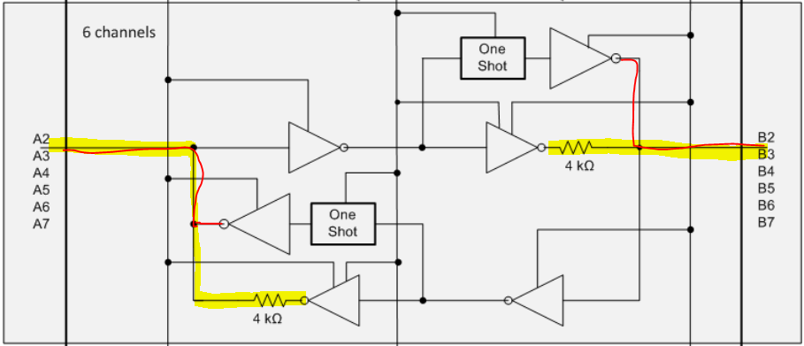
Customer uses voltage divider as below to convert signal.
Customer found an strange thing would like to check with us.
Taking example of green line below.
Ramping up the input from 0V at B4. Up tp around 14V, the output A4 will become "1", at mean time the voltage dividing point (mid of R1814 & R1836) will change from 3.xV to 5V.
Then rolling down input towards to 0V, when B4 is 3~14V, the A4 remains at "1" , until B4 is below 2V, then A4 change to "0".
Customer would like to understand if this behaviour is expected? And how it works internally?
Thanks!
Andrew


![[FAE] Andrew Wang](https://e2e.ti.com/cfs-filesystemfile/__key/communityserver-components-imagefileviewer/communityserver-components-avatars-00-00-07-45-83/4TN3ECJKFL7N.jpg_2D00_28x28x2.jpg?_=638280018663026000)