This thread has been locked.

If you have a related question, please click the "Ask a related question" button in the top right corner. The newly created question will be automatically linked to this question.

TXB0304: TXB0304 application

Part Number: TXB0304


Hi Dear expert,

My customer uses TXB0304 in their system. Below is their schematic. 

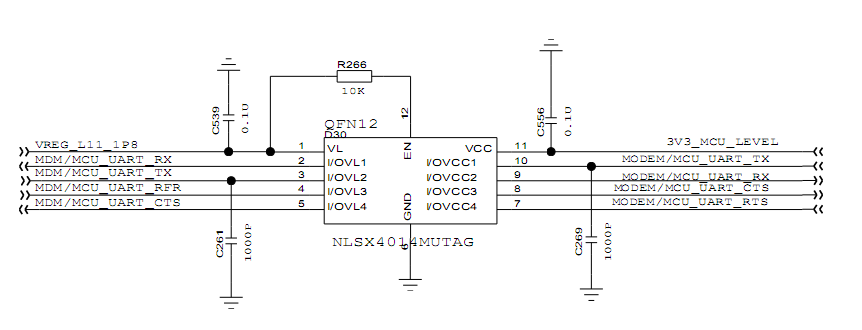
They used two channels: pin 2, pin 10 and pin 3, pin 9. The direction is pin 3 in 1.8V input, pin 9 is 3.3V output; pin 10 is 3.3V input and pin 2 is 1.8V output.

Now we found under this application, there is big overshoot at pin 9 3.3V output, see below scope snapshot. The overshoot could reach 4.43V max, and -0.96V min, which exceeds datasheet recommendation range.

What causes this overshoot and how can we improve this overshoot?

Looking forward to your reply.

Best regards,

Joyce

  • Hi Joyce Li,

    I see that there is NLSX device on the schematic. Please confirm that there is a TI device. I can't comment on another comp device.
  • Hi Shreyas,

    Thanks for your reply.

    Actually my customer has two vendors under this AVL code, one is TI TXB0304, one is NLSX4014. When testing NLSX, they also see the overshoot, but the overshoot voltage is smaller than TXB0304 and it is within the recommended ratings.

    The result I attached in the beginning is TI's result. Need your recommendation to mitigate the overshoot.

    Thanks a lot!

    Joyce

  • Hi Joyce,

    My recommendation for reducing the overshoot is to have very small value resistor in series ; may be 100ohm resistor should dampen the voltage.
  • Hi Shreyas
    Thanks a lot for your reply. Can you also explain what causes this overshoot? In datasheet, we didn't mention to put series resistor at the output.
    Do we have app note about this overshoot ?

    Thanks,
    Joyce
  • Joyce,

    Could consider doing an app note about this, thanks for the suggestion.

    The cause of the overshoot basically comes down to the impedance mismatch and due to the strong high-speed digital signals. The traces have series inductance and coupled with parasitic capacitance causes ringing. The one-shot circuitry is the high drive while the receiver being a light load can lead to overshoot and undershoots.
    A simple way to reduce this is to have series limiting resistance on the trace to dampen the ringing. This acts kind of like a low pass filter coupled with the parasitic capacitor dampening the high-frequency overshoot / undershoot and passing the low-frequency digital signal.

    Let me know if anything else.
  • Hi Shreyas,

    thanks a lot for your explanation.

    BR

    Joyce