This thread has been locked.

If you have a related question, please click the "Ask a related question" button in the top right corner. The newly created question will be automatically linked to this question.

LSF0108-Q1: Switch pass voltage

Part Number: LSF0108-Q1

Hi team,

I have a question for swithc pass voltage.

I am looking at the following expression in the datasheet.

"Rpu = (Vpu – 0.35 V) / 0.015 A"

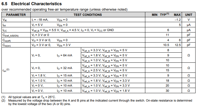
I understand that this formula limits the pass voltage to 0.35 V or less at 15mA, but can you think that it is satisfied at all temperature conditions?

In other words, is there no doubt that Ron of the switch does not exceed 0.35 V / 0.015 A = 23.3ohms under all temperature conditions?

In the data sheet ron is mentioned only typical, I do not know whether it can guarantee 350 mV or less even in the worst condition.

We are considering two patterns when Vref_A is 1.8 V and Vref_B is 3.3 V, Vref_A is 1.8 V and Vref_B is 5 V.

We must do it drop in the switch must be 350 mV or less even in the worst case.

Best regards,

Tomoaki Yoshida

  • Hi Yoshida-san,

    We do not guarantee the switch voltage across temperature for this device.

    The best solution to be absolutely certain that the output low voltage never exceeds 350 mV is to give at least 1 order of magnitude for 'safety margin' in your calculations.

    Using the given typical values:

    Since 1.8V to 3.3V is the worst case ron (18 ohms) in the above table, I will use that value. Giving a 1 order of magnitude margin of error, I will use 180 ohms for my calculations.

    From the LSF family "Logic Minute" video "Up Translation with the LSF Family":

    At V_BA = 350mV, the current through the LSF will be:

    I_B = 0.35/180 = 1.944 mA

    To then back-calculate the smallest pull-up resistor value, use the equation:

    I_B ≤ 5/(180 + Rpu) = 1.944 mA .... Rpu ≥ 5/(0.001944) - 180 = 2.392 kΩ

    For example, using a 10kΩ resistor would be extremely safe.  The one down side to using a large pull-up resistor would be that the maximum speed of the signal is limited by the load capacitance, as explained in the above mentioned video on this slide:

  • Hi Emrys-san,

    Thank you for your fupport.

    Since you explained in detail, I will refer to the setting of the pull-up resistor.

    Your support is very helpful for me.

    Why is not the maximum value of Ron defined?

    The user can select the pull-up resistor if maximum Ron is understood.

    I think that it is a sufficient margin to estimate with 1 order of magnitude Ron, but is there data to prove that it does not exceed the actual maximum Ron? 

    It is absolutely necessary to set it not to exceed 350 mV, so I want that information.

    Best regards,

    Tomoaki Yoshida

  • Hi Yoshida-san,

    Why is not the maximum value of Ron defined?

    That was a decision made when the part was defined - I do not have insight into why.

    Is there data to prove that it does not exceed the actual maximum Ron?

    Yes. I have characterization data that shows 3 lots of 30 parts each tested across temperature, and the absolute largest Ron seen during testing was 23 ohms (at high temp).

    We do offer an evaluation module if you would like to test the device yourself to determine its performance.  it's available here:

  • Hi Emrys-san,

    Thank you for your support.

    When Vref_A=1.8V and Vref_B=3.3V, Ron of the datasheet is 18Ω, but the measured worst is 23Ω.

    I understand that there is enough margin for one order.

    I'm will set Rpu to 2kΩ.

    I_B ≤ 3.3V/(180 + Rpu) = 1.944 mA .... Rpu ≥ 3.3V/(0.001944A) – 180Ω = 1.518 kΩ

    Since it is also used for SPI communication, Rpu can not be made too large.

    If Vref_A=1.8V and Vref_B=5V, since Ron of the data sheet is 10Ω, is it enough to estimate with 100Ω?

    Best regards,

    Tomoaki Yoshida

  • Hi Yoshida-san,
    Yes, I think estimating with 100Ω is extremely safe.