This thread has been locked.
If you have a related question, please click the "Ask a related question" button in the top right corner. The newly created question will be automatically linked to this question.
Hello!
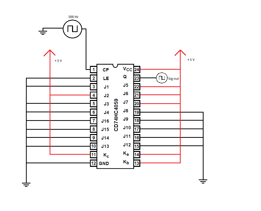
I've developed a frequency divider using the said part number based on the help of a previous thread. Though, we only discussed the J and K pins on that thread, and nothing else.
Notes:
My Issue:
Please help! I am not entirely sure what to do with the LE pin.
Thanks in advance,
Gage
Hi Gage,
Yes, Vcc = HIGH, and GND = LOW.
From the datasheet:
A “high” on the Latch Enable input will cause the counter
output to remain high once an output pulse occurs, and to
remain in the high state until the latch input returns to “low”.
If the Latch Enable is “low”, the output pulse will remain high
for only one cycle of the clock-input signal.
For your application, I would recommend setting LE = GND.
Can you provide a schematic for your test setup?
Also, if you have scope shots for your input signal and the output you are seeing it would be helpful.
Since your signal is very slow, make sure to get a zoomed in view of the edges (rising and falling) for the input. We are looking for fast/sharp input edges.
Hi,
I installed the schmitt-trigger before the circuit, and it seemed to make the output more consistent, but the "divide-by" number seems to be much larger than expected. I set N=15, and with an input frequency of 500 Hz, the output frequency was about 1 pulse per 4 seconds. Thoughts?
I've done some experimenting the last few days. I looked over the example given in the DS and the realized that we made an error. In Mode 2, J1 is the only input for the remainder, therefore when I had J2 = H, it considered that jam to be in the 1000's place.
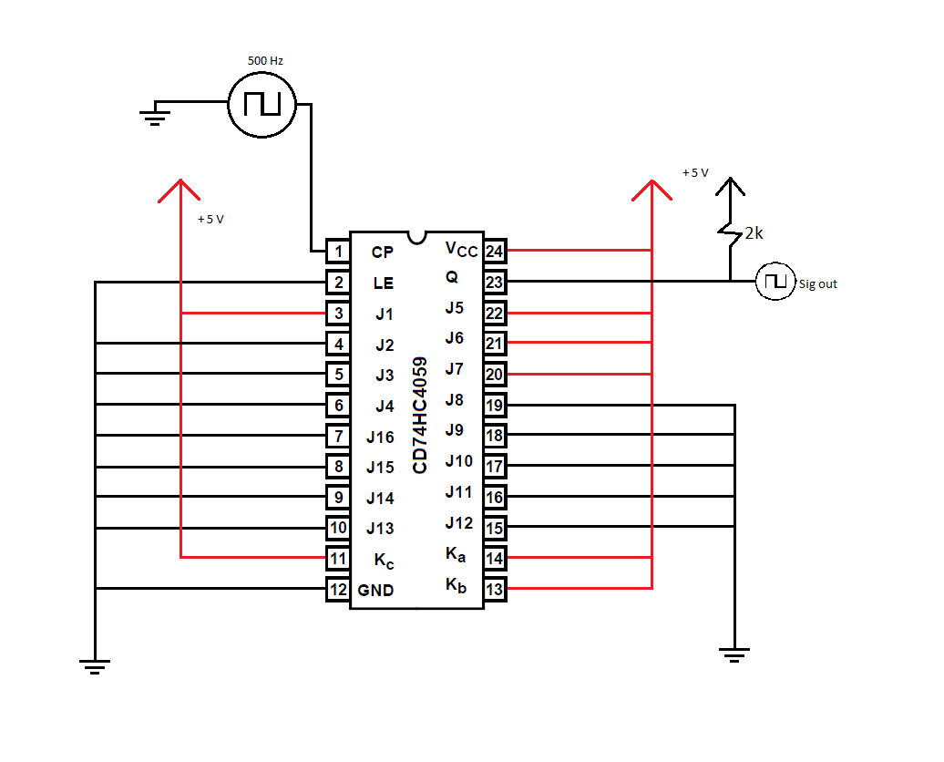
I just rectified this problem, but now I'm thinking about another issue: the output signal is pretty noisy. I have 36058 RPM at the input, and the output is jumping around 3200 +/- 1000 when it should be 2400 RPM. I played around and installed a 2k resistor between output signal and Vcc, and this seemed to help a bit, but not enough. Now the output signal bounces between 2500-2800 RPM. I've tried different valued resistors, but they either seem to make the noise worse, or make the signal drop to 0 V. I've also tried installing a cap in-place of the resistor, but it didn't help. Maybe I should try a cap and resistor in parallel?
Here's the interesting part: if i touch my tube scope to the output, the signal becomes much more stable and hovers around 2500 +/- 10 RPM. Thoughts?
Take a look at my new circuit below:
Hey Emrys,
Yes, I did some more testing and got a circuit that I am satisfied with! I installed a 0.1 uF cap in parallel with the 2k resistor and the signal seems to be much more stable. We are now getting some prototype PCB's made and will be testing it further.
Thanks for all of your help!
-Gage