Because of the holidays, TI E2E™ design support forum responses will be delayed from Dec. 25 through Jan. 2. Thank you for your patience.

This thread has been locked.

If you have a related question, please click the "Ask a related question" button in the top right corner. The newly created question will be automatically linked to this question.

SN74LVC2G07: Working with 5V VCC and 3.3V Input Signal

Part Number: SN74LVC2G07
Other Parts Discussed in Thread: SN74LV4T125

Hello,

I have a small question regarding the workflow of the SN74LVC2G07 part. From the table on page 3 of the datasheet we can see that for 5V VCC the High level Input Voltage should be 0.7 x VCC, i.e. 3.5V. What happens if it is lower? I have 3.3V input voltage, what will I have on the Output? (I assume still high level but a bit lower...?)

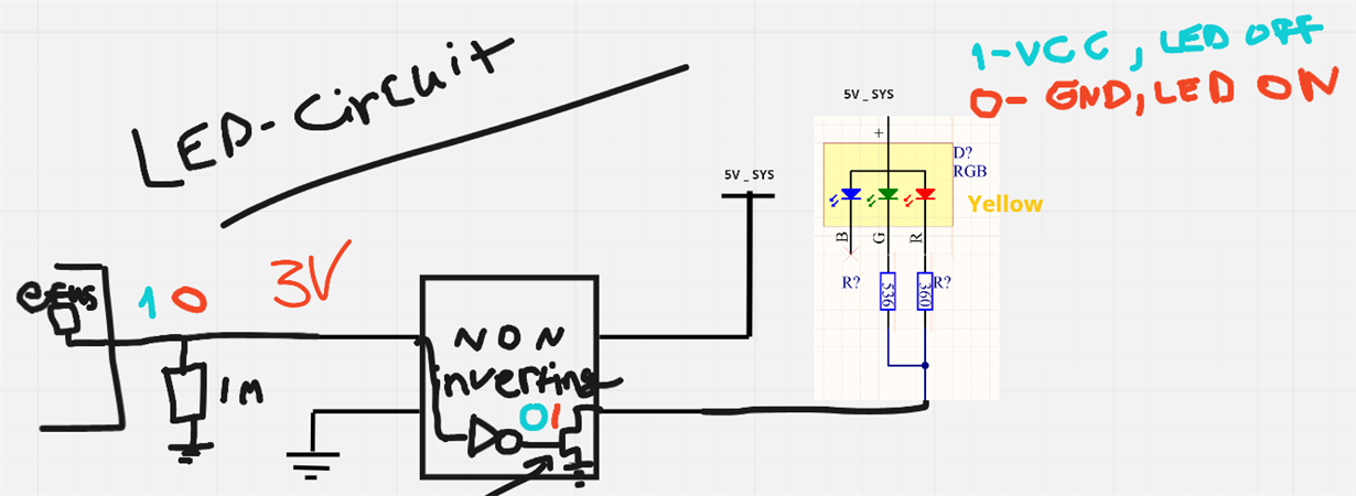
I basically want to drive a LED with this part. The LED is connected to 5V and should be controlled with a uC. (see image below) 

Kind Regards,
Den

  • Hi Den,
    The "High Level Input Voltage" in the datasheet indicates the _minimum_ input voltage that will guarantee the input is correctly read as a "high" input. Below that value, you could excessive current, oscillating outputs, and damage to the device (or worse, damage to your supply due to the excessive current).

    Do you have a 3.5V supply available on your board? It would be ideal if you could just power the SN74LVC2G07 from that instead to fix your thresholds. The output is unaffected by the supply value since it is an open-drain part.
  • Nope, I only have 5V immediate voltage and 3.3V when my uC is up. I wanted LEDs to light up before uC is running since it takes up to 5 seconds for it to boot up (it's a module). Customers should see some immediate response and not wait for 5 secs. Do you have a part which will work with 5V VCC and 3.3V input voltage?
  • Hi Den,
    I don't know of any TTL-compatible (ie 2V input threshold) devices that are also dual buffers.

    The one option I can think of is the SN74LV4T125 -- this is a 4 channel 3-state buffer.
  • Do you mean CMOS? Because TTL has a low threshold since it's Bipolar, or am I mistaken something?
    How did you come up with 2V? (just academic curiosity)

    Regardless, it seems that there are no open drain buffers that work with this configuration. Could you suggest a good 2 Ch 3-state buffer? (4 is an overkill) which will be suitable for my application?

    Kind Regards,
    Den
  • For your application, you don't need open-drain.  If the output of the buffer is 5V, and the diodes are also connected to 5V, no current will flow.  Any buffer will work.

    You are correct that TTL specifically refers to BJT logic, but today there are also TTL-compatible CMOS devices.  Here's a chart showing the input/output voltage differences:

    That's a screenshot straight out of TI's logic guide: