Other Parts Discussed in Thread: TEST2
Dear team,
Our customer found that errors appeared in some channels of TXB0104 when every channel has input signal. I did some tests shown in below. And VCCA=OE=1.8V, VCCB=3.3V, input signal is f=1kHz, amp=1.8V square wave.
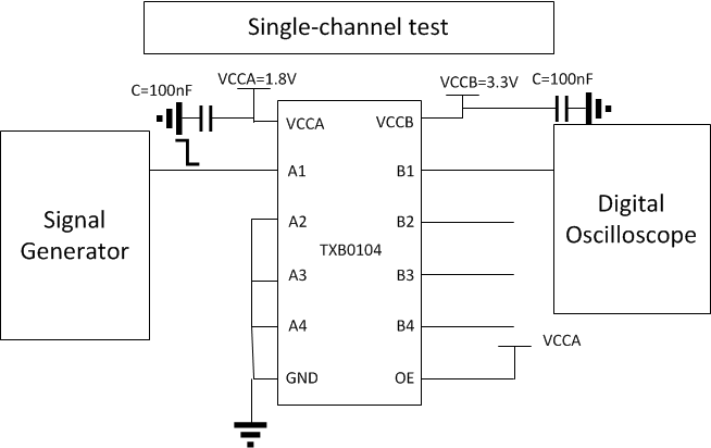
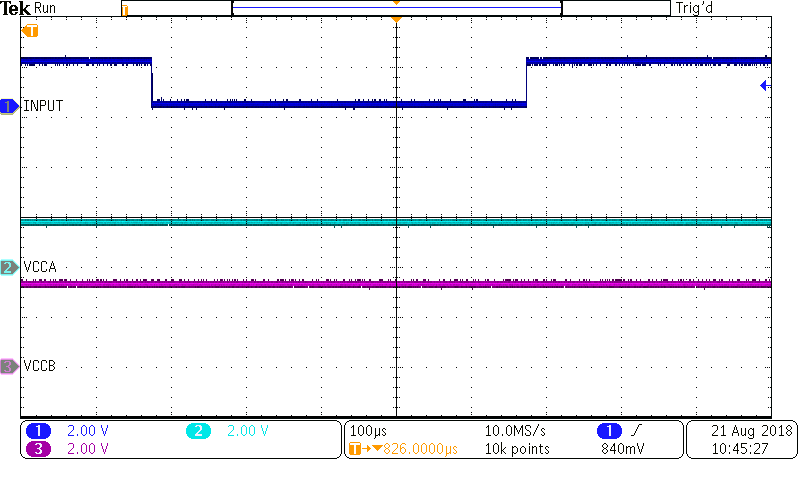
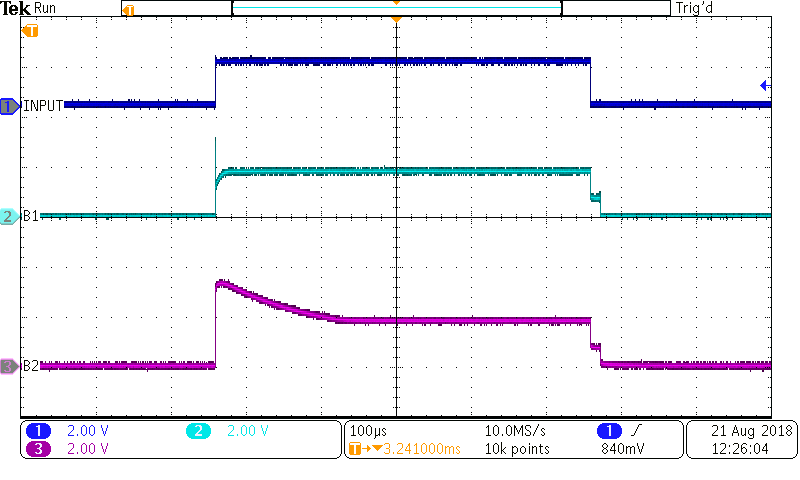
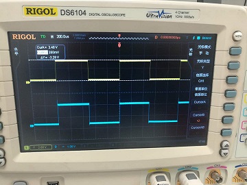
- A2B single channel test is operating correctly. For example, A1 is input, and B1 output waveform is correct when A2-A4 is grounded. Attachment1 is test result. The blue line is input, the yellow line is output.
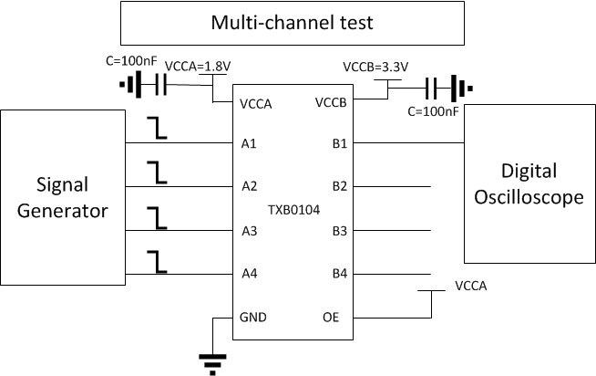
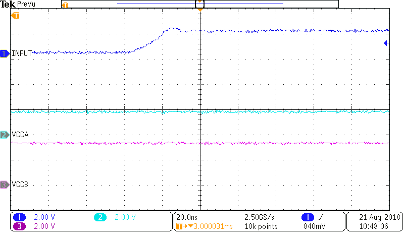
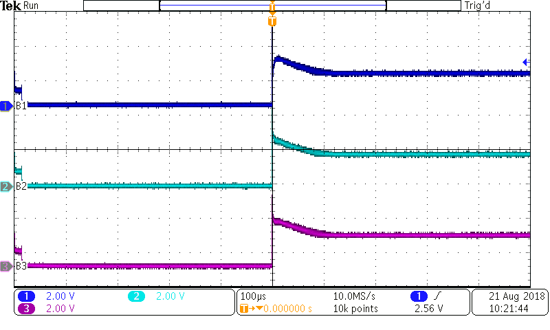
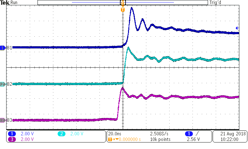
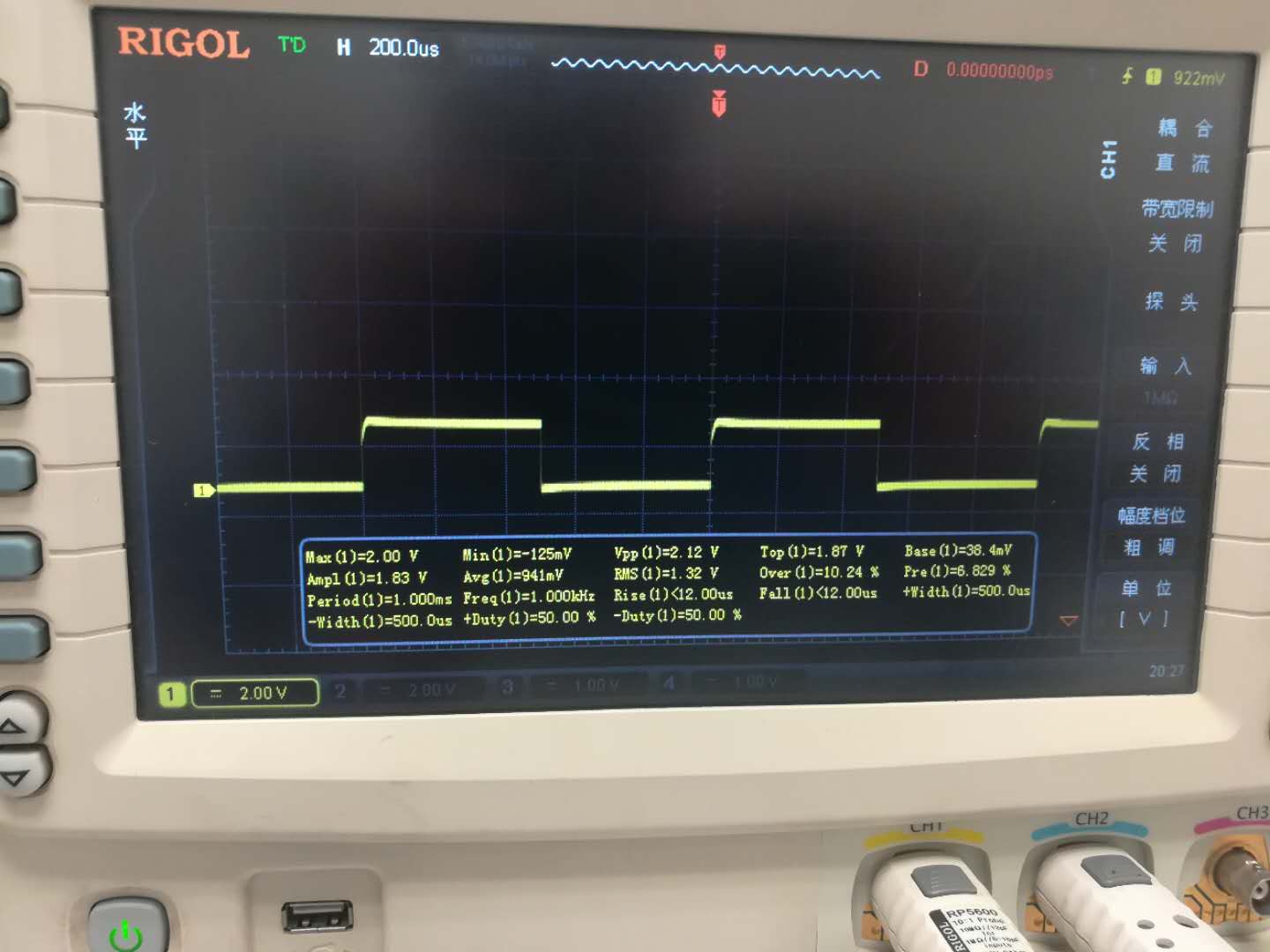
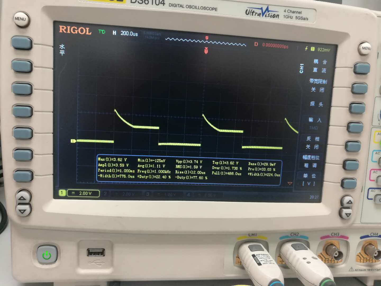
- A2B multi-channel test is abnormal. When IN=A1=A2=A3=A4, B1-B4 are all abnormal. Attachment2 is the test result of B1 and B2 while B3 waveform is close to B2, and B4 waveform is close to B1.
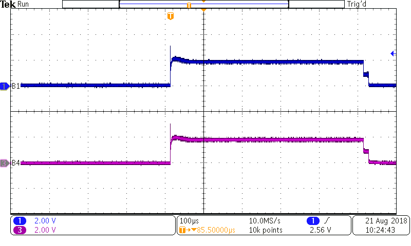
- I added 65KΩ pull-up resistor between B1-B4 and VCCB based on test2, and the output waveform became correct.
- B2A test is correct whether in single channel or multi-channel test. (In B2A test, input signal is f=1KHz,amp=3.3V square wave, output is amp=1.8V square wave)
- I measured ICCA and ICCB when VCCA=OE=1.2V, VCCB=3.3V.ICCA is 0.005uA and ICCB is 0.5uA when VI=GND. And on the other hand, ICCA and ICCB both are 20uA when VI=VCCA. The ICC result is strange enough.
Attachment1:
Attachment2:
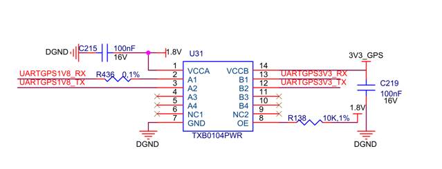
This is customer schematic circuit.
Thanks!