Thank you for reading my issue!
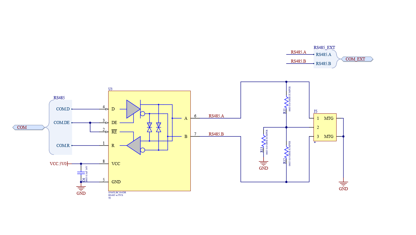
I have attached the schematic showing how the SN74LVC1G34DBVR is designed into the product.
I've had (2) of these chips exhibit very low R between 5V and GND pins on failed PCBs. One showed 9.48 Ohms and the other roughly 14 Ohms.
On the PCB, in circuit, right at power up these 2 devices pulled the 5V supply down to "GND" and caused a blow of the 5V regulators on those 2 PCBs. Note: The PCBs with blown regulator and "errant" U4 had been powered up 2 times at the factory - once to load firmware and once to verify response after assembly into enclosure - with no PCB damage DETECTED. The failures occurred at power-up at customer site....since the PCB is in an enclosure when it arrives at the customer, I can't imagine ESD would be an issue at the customer not a big deal, just need to understand how this could happen.
Our PCB is in a conductive enclosure and the PCB GND is attached to the enclosure through PCB mounting holes. PCB is screwed into enclosure. These devices are installed into large water pipes where the PCB is external to the pipe, but electrically attached through the enclosure to the pipe...the pipes may be "grounded". THe PCB is powered from whatever 24V supply the customer has chosen..could be up to 250W at 24V.
The SN74LVC1G34DBVR chips do not look damaged and they do have a 100 Ohm protection resistor on their output - I have verified those resistors are there and are the proper value. I have also measured and verified the health of TVS1.
I have several PCBs here where U4 is OK and not pulling 5V supply down...out of 100 PCBs MFG, thus far I have found 2 that are LOW R and 1 that is 1.4M Ohm...what should I measure between pins 5 & 3?
Finally, and Interestingly, we have never seen this anywhere except at 2 customer sites...