This thread has been locked.

If you have a related question, please click the "Ask a related question" button in the top right corner. The newly created question will be automatically linked to this question.

SN74LVC1G123: Output Pulse duration

Part Number: SN74LVC1G123

Hi,

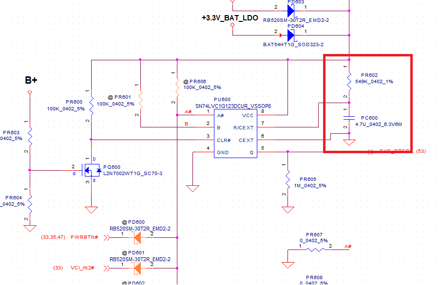
Is the duration decide by PR602 and PC600?

In this application the Q duration should be 2580ms, am I right?

Is there exist any limitation for R and C or Q’s pulse time?

Best regards,

Randy Chen

  • Hello Randy,
    Yes, the output pulse width is determined by PR602 and PC600 in the above schematic.

    It looks like the supply voltage will be approximately 3.3V, so we can use the 3.3V plots for the K factor.

    I'm guessing that the capacitor value is 4.7uF? And the resistor value looks to be 549kohms.

    We need the "K" value from the datasheet to calculate the pulse width. This is found in figure 6 usually, however you have a capacitor value that's pretty far off the chart. I would start with an estimate of K = 0.9, but a prototype would be required to determine the actual value. I can only guarantee values for what is listed in the datasheet.

    The output pulse width is: t_w = K * R * C = 0.9 * 549000 * 0.0000047 = 2.32s

    [edited to correct equation, 8/29/22, Emrys Maier]

    I would expect it to be in that range -- as I mentioned above, prototyping would be required to determine the K value for the selected capacitor.

    Additionally, there is some leakage into the device, and with such a large resistor, you could see some change in the final pulse width due to that as well. I try to keep my resistor values below 1 Mohm, but 550k is starting to get into that territory and could see a significant voltage drop just from leakage current.