This thread has been locked.

If you have a related question, please click the "Ask a related question" button in the top right corner. The newly created question will be automatically linked to this question.

SN74AHC595: Have drop at the rising edge of sn74ahc595

Part Number: SN74AHC595

Hi team,

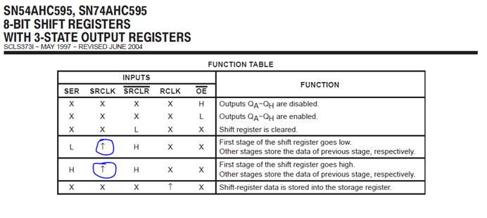
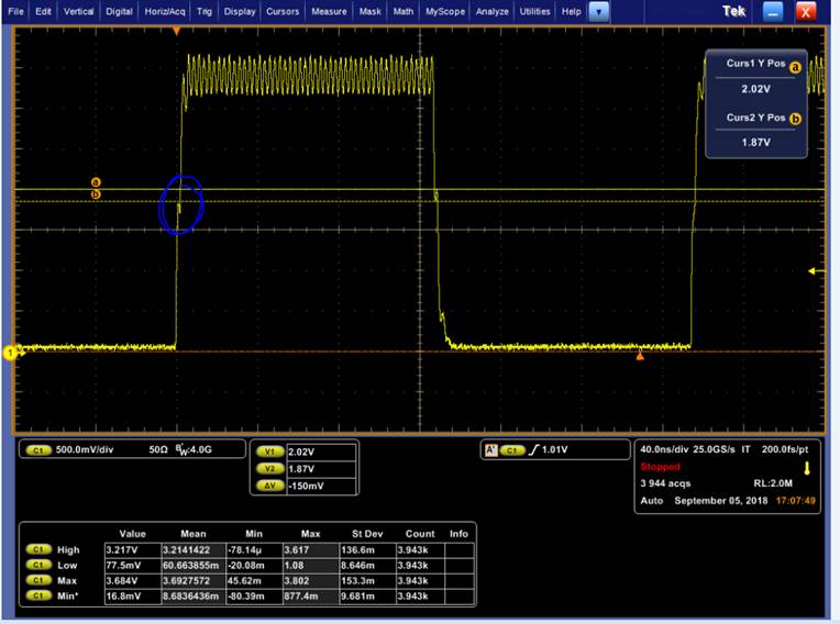
my customer is using the SN74AHC595 now. And we meet the drop of the rising edge. Whether it has risks.

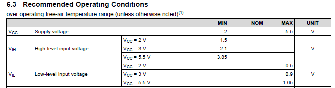
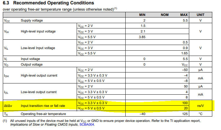
based on the datasheet, we get the devices CLK is based on the rising edge. i want to know how to decide the rising the edge. We calculate the Δt based on the 

0V to 2.1v time, right? Thanks. 

  • Hello,

    Typically the positive edge will be triggered at the V threshold for the device. Since this is a balanced CMOS device, the threshold voltage will be around 1/2 Vcc. Vih and Vil ratings provide a min and max region in between which is the threshold at which the device switches from low to high. The exact value of the threshold is not known but at 3V, it would be between .9V and 2.1V. Based on your scope shot, the first drop you get is close to 1/2 Vcc which might trigger a false positive edge. You can test this on the device to see if this is actually causing a false positive edge however, there is no guarantee we provide on where exactly the threshold voltage is.

    Do you think you can use a schmitt-trigger input buffer to clean out this rising and falling edge?

    Thanks!

    -Karan

  • Hi Karan,

    Thank you for your reply. We want to check the items below;
    1. how to calculate the Δv/Δt, use the 3.3v or 2.1v or 1.65v.
    2.Do we have hysteresis value of the VIH and VIL, or just use the datasheet data. 2.1v, 0.9v, so the hysteresis is 1.2v.
    3.When we design with logic device, what we need to think besides the Δv/Δt.
    Thanks.
  • Hi,

    1. The minimum required transition rate is listed in the datasheet as follows:

    You need to make sure your transition rate for this device since you are operating near 3V is faster than 100ns/V.

    2. This is not a schmitt-trigger input device and so there is no hysteresis. As I mentioned, the Vt which is Vthreshold is the voltage at which the device changes from a low to a high, or a high to a low. Vt = Vcc/2. So if you were using 3V Vcc, then the Vt would be around 1.5V. This means when your input signal is 1.4V then the output would be a low and if your input signal is 1.6V then your output would be a high. However, you should never operate your input signal so close to the threshold voltage because this causes tons of current draw.

    For this reason, a VIH of 2.1V is listed and VIL of .9V is listed as the min and max input voltages for a high and a low. I see that your glitch is occurring near 1.5V and for this reason I mentioned that the device might cause a false positive edge trigger. You might want to use a schmitt-trigger input which allows hysteresis to avoid this issue.

    3. Here is an appnote on designing with logic: 

    This appnote is fairly old so be careful of the voltages and family names mentioned. 

    If you look on the right side of the following page, you will see a list of our FAQ questions, which you can go through to get a understanding of common issues our customers face when designing with logic:

    Thanks!

    -Karan