This thread has been locked.

If you have a related question, please click the "Ask a related question" button in the top right corner. The newly created question will be automatically linked to this question.

TXS0102-Q1: How to connect OE pin

Part Number: TXS0102-Q1
Other Parts Discussed in Thread: TXS0102

Hi,

Customer is using a GPIO from AMD CPU to control OE pin of TXS0102-Q1.  Meanwhile, the same GPIO is also used to control the EN pin of another chip.  Can you suggest how to calculate the pull-down resistor value that should be connected to OE pin under such application scenario?

We see"The minimum value of the pulldown resistor to ground is determined by the current-sourcing capability of the driver." in the datasheet, but still not sure how to calculate this.

THanks!

Antony

  • Hi Antony,

    I think this should help:

  • Hi Emrys,

    Thanks for your reply.  From the link you sent, I think we should be the first of case of (1) Drive Current for which we need to calculate the pull-up resistor value based on the Vol spec from customer's CPU GPIO spec.  But, what I don't understand is, why the typical application from TXS0102_Q1 spec shows a pull-down resistor at OE pin as below?  When should we implement a pull-down resistor like this instead of a pull-up resistor?  

    Thanks!

    Antony

  • Hi Emrys,

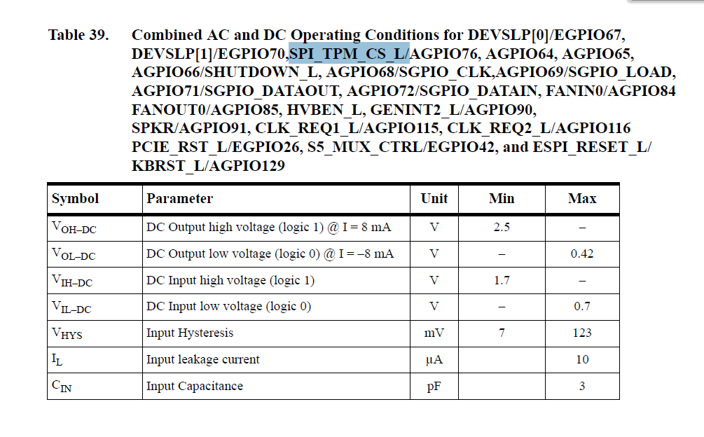
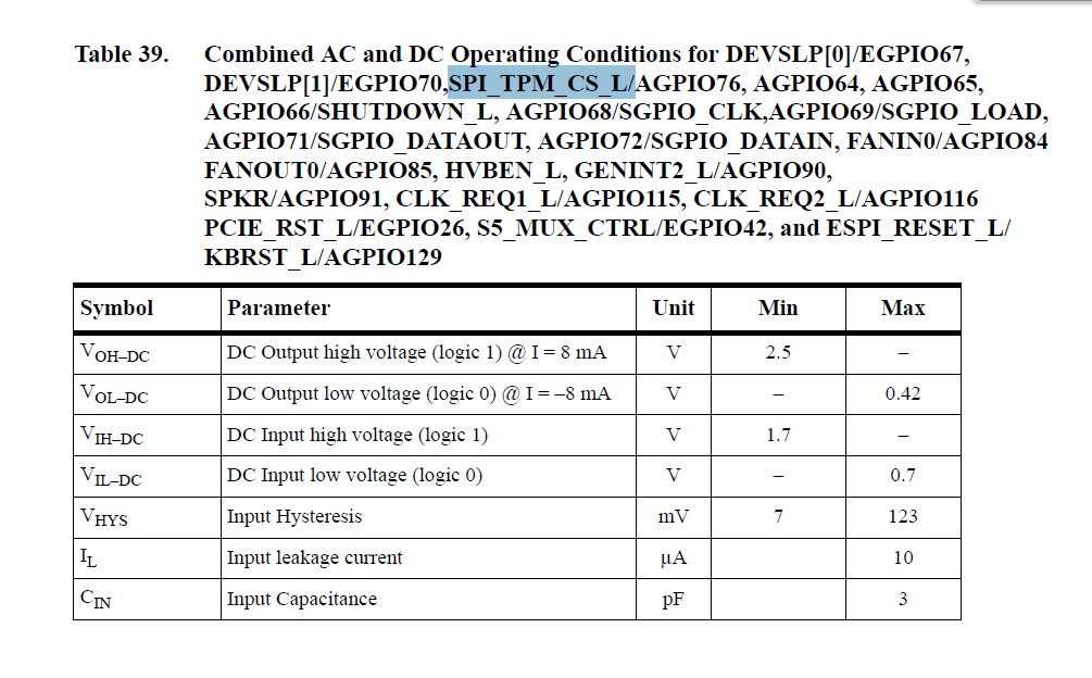
    In parallel, please check below for the Vol spec of the signal which is connected to our OE pin.  Please provide your comments accordnigly.

    Thanks!


    Antony

  • Hi Antony,
    This pull-down resistor is used to hold the OE pin low when the system controller is turned off, thus disabling the TXS0102-Q1. The question of "should we do this" will depend on the system design... what does the customer want?
  • Hi Emrys,

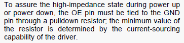
    Based on the description quoted from the datasheet as below, it looks to me it's a requirement from TXS0102-Q1 spec to make sure OE is at high-impedance state during power up.  If this is a requirement TXS0102-Q1 and meanwhile customer is using a GPIO to control OE, how should customer judge how to implement external pull-up/pull-down resistor on OE pin?

    Thanks!

    Antony

  • It is based on the system requirement. "To assure the high-impedance state" is not the same as "You absolutely must start the device in the high-impedance state" -- do you see the difference?

    This is a decision that must be made by the customer based on their system requirements.
  • Hi Emrys,

    Thanks for the explanation.  Considering customer wants to implement the pull-down resistor to hold the OE pin low when the system controller is turned off, how should we judge the pull down resistor value?

    Thanks!

    Antony

  • Hi Antony,
    That is explained in detail in the FAQ I linked previously. Are you having trouble with some part of the calculation?
  • HI Emrys,

    The example in the FAQ you linked is implemented with an external pull-up.  Now, my customer implemented it with external pull-down from a GPIO with spec as below.  So, my calculation should based on the Voh (2.5V @ 8mA) which means the R value should be bigger than 2.5V/8mA=312.5ohm, right?  Now they implemented it with 499kohm which is much bigger and may cause bigger leakage, so I think we can suggest them to try a value around 1kohm, correct?

    Thanks for your support.

    Antony

  • Resistors work the same way if they are pull-ups or pull-downs (V=I*R) which you have correctly determined. I will make a note to add this to our FAQ.

    Selecting the minimum size resistor will also waste the maximum amount of power (P = V^2/R), so it's generally a good idea to increase that a bit, and 1k will probably be an OK value.  Let's check.

    You seem to have ignored the second half of the FAQ which talks about the timing component of selecting a resistor value.

    If the resistor is selected at 312.5Ω (the smallest value that can be used based on the 8mA limit given), then the rise time of the signal will be approximated by:

    t = 3*R*C

    I'm going to assume 15pF load -- the fall time is calculated as ~4.69ns.  The TXS0102-Q1 has an input transition rise or fall rate requirement of 10ns/V -- at 1.8V operation, that is 18ns total rise time (max).

    We can use that to go back and calculate the maximum resistor value that will work:

    R = t/(3*C) = 18ns/(3*15pF) = 400 Ω

    Assuming that my estimated load is accurate (15pF is just a typical value, the actual value may be larger or smaller), then the resistor value can be:

    312.5Ω ≤ Rpu ≤ 400Ω

    Just to be very clear, if I had assumed a 5pF load (ie very short traces and only 1 CMOS load), then we would get a different answer:

    R = 18ns/(3*5pF) = 1.2kΩ

    This is heavily determined by the customer's system -- the VOH of the previous stage, as well as the parasitic loading of their board layout. The more you (and I) know about their system, the better we can help them.