This thread has been locked.

If you have a related question, please click the "Ask a related question" button in the top right corner. The newly created question will be automatically linked to this question.

CD74HCT7046A: HCT7046 noise

Part Number: CD74HCT7046A

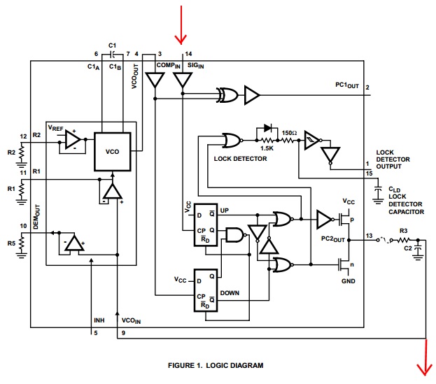
We are now using HCT7046 for FM demodulator design, the sch is same as datasheet FIGURE 1. LOGIC DIAGRAM as below, R3=3.3k, C2=470pF. signal frequency(intermediate frequency) applied on pin14 is 10.7MHz, 280kHz bandwidth, power supply is 5VDC.

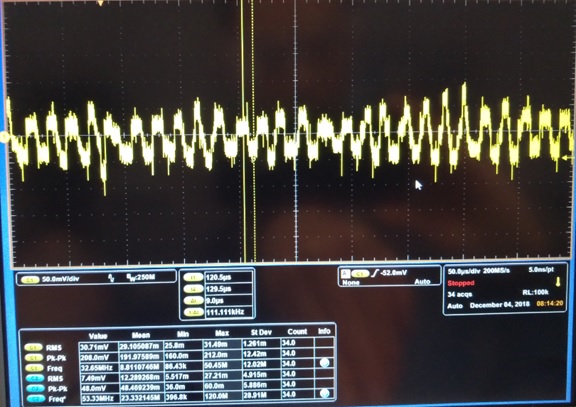
LD signal on pin1 is always high so PLL is locked well, power supply noise is very small, and the 10.7MHz signal is very stable, the converting function between input frequency(on pin14) and output DC voltage(on pin10) is good. but the signal on Demo_out pin10 has noise with frequency between 12kHz to 70kHz and with amplitude of 40mVpp. We have taken many trials to remove this noise or try to move this noise to high frequency for LPF easily remove, but the noise is very very hard to change.

This noise frequency range is overlaped in signal band, so my question is if this noise is normal component in the Demo_out signal? how to remove this noise? or if this noise can't be removed how to move the noise frequency to higher end up to several hundred kHz for easily LPF kill?

Thanks!

  • Hello,
    I think what you are seeing is oscillation caused by instability in the unity gain VCO_IN to DEM_OUT amplifier.

    I would recommend three possible fixes -- first, you can try increase the resistance at R5 to reduce loading of the amplifier. This is the only way I know to improve stability of the amplifier that's embedded in the IC.

    Next, you can add a damping resistor (~100 ohms) in series between pin 10 and R5 to isolate the output of the buffer. Both of these first fixes are intended to improve stability of the amplifier.

    The other option is to use an external amplifier to buffer the signal at VCO_IN for DEM_OUT. This option gives you much more freedom to improve the buffer circuit (choosing a better opamp) and eliminate any oscillations/noise with appropriate feedback/compensation.
  • Duo to TI E2E performing maintenance so reply delay.

    Thanks Emrys Maier for your remindings, we have took the test to enlarge R5 resistance and series 100Ω  resistor to isolate load, the noise have not any changing. We also use external OPA AD8606 to buff(unit gain) the signal at point of R3/C2 as FIGURE 1 red arrow showed, the noise also keep unchanging.

    Meanwhile we take signal photo at R3/C2(same as at pin9 VCOin) as below. I think this noise likely generated by HCT7046 demodulation principle, or the FM signal feed to pin14(SIGin) have some phase noise and people eyes cann’t identify the waveform jitter on O-scope…

  • Thanks for the detailed response.

    I had hoped this was similar to a different issue I had seen before.

    The only other option I could think of would be to swap the RC output filter to an active filter with a much sharper roll-off to eliminate the excess noise.

    It's entirely possible that this noise is just something that is inherent to the HCT7046 -- it was designed a long time ago by Harris Semiconductor, and I don't see any stringent noise specs in the datasheet that would indicate they tried to prevent this kind of effect.