This thread has been locked.

If you have a related question, please click the "Ask a related question" button in the top right corner. The newly created question will be automatically linked to this question.

SN74LVC1G99: Logic function of XNOR not available

Part Number: SN74LVC1G99

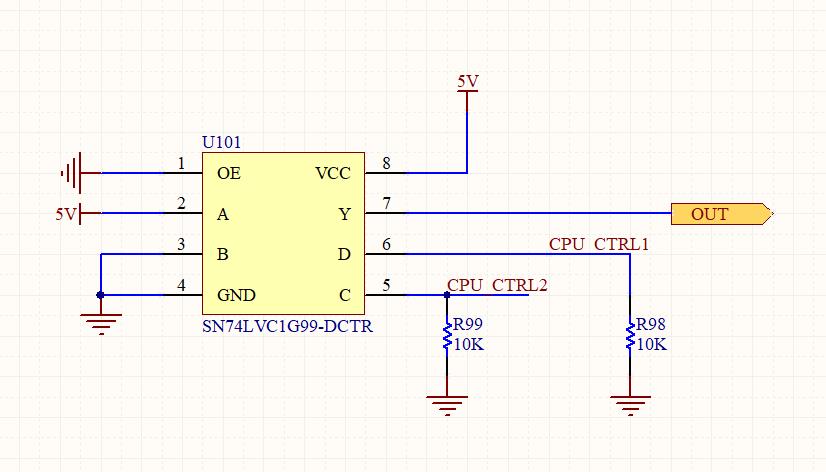
My Schematic  is as shown above。when I change the input logic of the SN74LVC1G99 PIN C and PIN D,PINY always output low,I've tried several times, I donot konw why。I hope TI engineers can help me solve problems,Thanks very much。

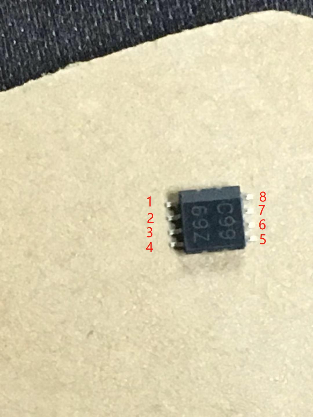
I bought chips from MOUSER,The SN74LVC1G99 IC picture as follows:

  • Hi Peter,
    Your schematic is correct -- that means the issue would have to be somewhere else in the system that you aren't showing me. It could be something as simple as a short, or it could be a more complex issue like ESD damage to the output of the SN74LVC1G99, or a load that can't be driven by this device.

    I would recommend starting by checking that the inputs are doing what you expect on an oscilloscope, and monitor the output and supply to see if either fluctuates during operation.

    Next I would start looking closely at everything connected to the traces or wire that has the erroneous signal on it.

    If you can provide a complete schematic and layout, i can try to see any issues from here.
  • I'm sorry that I didn't reply to you in time because of my business trip two days ago.
    Because I can't upload pictures, I directly dictate the connection mode of the test circuit. The IC PINs 1,2,3,4,5,are directly connected to ground. PIN 6 pull-down and connected to a switch and then to the power supply(5V). PIN 7 as output point. PIN 8 connected to the power supply(5V).
    I used an oscilloscope to measure the input voltage at all test points correctly, except the output point.
    When I change the logic of PIN6(D),there is no logical change at the output point (Y). This result is different from the truth table I queried in the data manual.
    I wonder why. I've tried many usual testing methods. All the output points have no logical output. I also changed several chips.
    If there is no problem with the chip you are testing, can you send the test circuit to me for reference?
    Thank you very much.
  • Hi Peter,

    You can upload images on e2e. It would be very beneficial to us to see some scope shots of your operation.
  • Hi Peter,

    Have you tried replacing a different device(preferably from another order) or is this the only device tested?