This thread has been locked.

If you have a related question, please click the "Ask a related question" button in the top right corner. The newly created question will be automatically linked to this question.

SN74LV1T45: Schematic review / pull-up resistor requirement

Just another question concerning LVCT components, Do I have to place some pull up resistors between 1Y and B / 2A and B1 / 2OE and B2 (and same on the other side).
It is said on datasheet that " SYSTEM-1 and SYSTEM-2 must use the same conditions, that is, both pullup or both pulldown."

Also, I guess I shall use some capacitors for Vcca and Vccb and a same pull up resistor for direction.

Am I correct ?

Thanks again

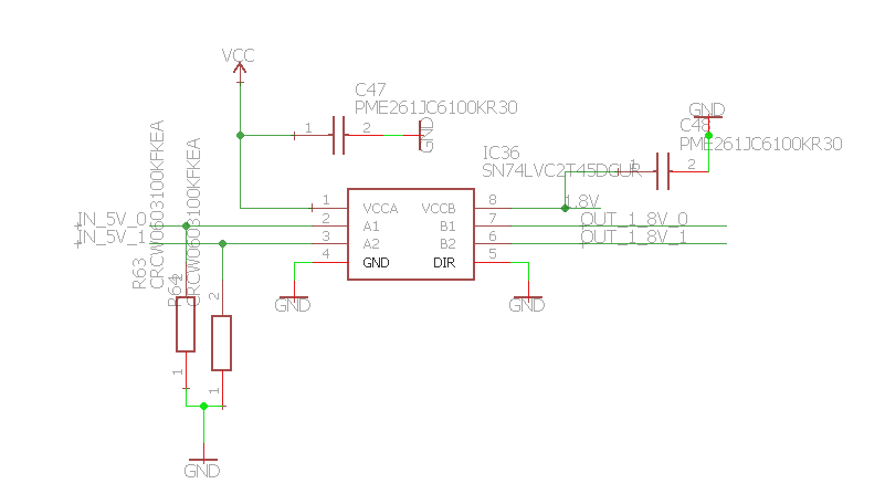
Here's what I've done with Eagle (resistors 4,7K ohm and capcitance 100 nf) :

  • Hey Thibault,

    I split this thread to separate out the questions. This helps anyone who might come along looking for info regarding a similar question.

    The resistors R61, R62, R63, and R64 can be removed entirely (open circuit). These are all connected to outputs which will always be driven directly by one of the logic devices -- there will never be a time when those lines are left floating.

    The resistor R60 can be left there or removed (short circuit) -- it is connecting only to a high impedance input (DIR), and thus provides no benefit to the circuit.

    I would recommend adding a pull-up or pull-down resistor at I/O_VOIE1_TTL_0. This is a node that can be left floating (if ~2OE is de-asserted and the output is not connected to anything).  A very large pull-down can be used to reduce loading issues (for example, 100kΩ)

    I also had a couple of recommendations for your schematic in general, these aren't necessary, but are general design practices that will help you in the future:

    (1) Pinouts in the schematic don't have to match the datasheet.

    You may already know this, but I just wanted to mention it if you didn't.  Many engineers rearrange pins in the schematic to make their designs look cleaner and to prevent confusion.  I noticed that all of your pinouts are pin-to-pin matches for the real devices --- there's nothing wrong with that (especially for hobbyists... it makes it much easier to wire things up!), but with larger chips it can be very  beneficial to place pins out of order.

    (2) Avoid crossing pins

    Be very careful about crossing pins with wires -- some programs dont' have a problem with it, but some will short the wire to the pin, and you may not notice.

    It is very easy to overlook this kind of thing, and it's very hard to hunt down the issue when you get PCB's fabricated.

    (3) Avoid4-way intersections

    This is another software issue -- sometimes programs won't properly connect all wires at an intersection. If you have 4 wires going into the same point, it's possible for one of them to not be connected, but there's still a junction bubble so you can't tell. It's a good practice to separate out 4-way connections into 2x 3-way connections, just for clarity.

    Good luck with your project, and come back any time.

  • hey Thibault,
    Sorry, I left out info on the capacitors!

    Yes - you should have a bypass capacitor at the supply pin for each device, preferably placed as closely as possible to the physical pin as you can. These capacitors are typically 0.1uF, but can be basically any value beween 0.022uF and 1uF... and some engineers even add multiple capacitors in parallel to help eliminate certain bands of noise. If you aren't expecting problems with high frequency noise, I would suggest just 0.1uF caps.
  • Ok thanks for your answer very clear.

    It help me a lot understanding components and how to proceed.

    So you told me this " The resistors R61, R62, R63, and R64 can be removed entirely (open circuit). These are all connected to outputs which will always be driven directly by one of the logic devices -- there will never be a time when those lines are left floating." which I understand.

    Now if I was in the following configuration (with 2 5V inputs coming from a connector (sub for example) and I connect them directly to LVC2T45), should I need some pull down resistors (I take 100K in my example):

    Thanks

  • In this schematic, the LVC2T45 is configured with A1 and A2 as outputs (DIR = LOW), so the pull-down resistors are not required. If you configure the A1 & A2 pins as inputs (DIR = HIGH), then I would recommend using pull-down resistors to keep the inputs low when the connector is disconnected.

    I should note 1 other thing -- I would recommend adding external ESD protection between the connector and the logic devices. The internal ESD protection in these devices is only designed for manufacturing ESD protection -- most events from human contact are much higher voltage and can cause damage to the devices.