This thread has been locked.

If you have a related question, please click the "Ask a related question" button in the top right corner. The newly created question will be automatically linked to this question.

SN74ACT14: How fast can these things toggle? I'm Having's problems with a 500kHz switch circuit.

Part Number: SN74ACT14

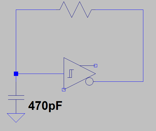
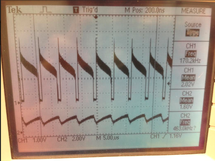
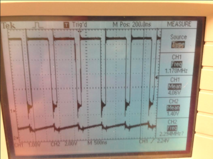
I am trying to switch the output at ~500kHz.

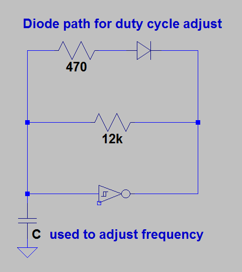
There is a feedback resistor that charges/discharges a capacitor on the input. Depending on what socket I use or if i am using jumper wire or not determines weather the output oscillates correctly.

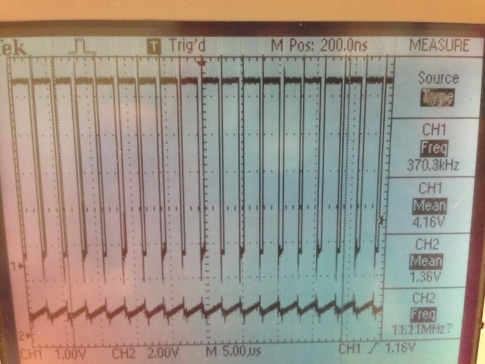
Sometimes I can see it oscillate for a few pulses before it stops.

Whats is the max frequency for these parts? The datasheets shows 1MHz test condition using a signal generator (meaning I would have use half that for feedback input) but is that the MAX frequency?

Thanks

Tony

  • Hi Tony,

    There's an FAQ on max frequency here:

    For the SN74ACT14, I would expect it to cap out around 90 MHz.

  • Hmm, Ok so that's not the problem.

    Is it possible that the gain is not enough on these parts, or just barley high enough to make an astable oscillator?

  • Hey Tony,
    If I remember right, the gain required for an oscillator is typically pretty low, and logic devices typically have gain in the 10k or higher region.

    Do you have scope shots of the device when it's operating and when it's not?
  • Hey Tony,
    I'm going to close out this thread for now. If you need additional help or have found a solution, I'd love to hear back from you.
  • Hey sorry I got side tracked with another project.

    Gain is definitely the issue. When the frequency is set too high it seems like the parts start to regulate within the hysteresis region. Also when approaching this frequency the circuit becomes extremely sensitive.

    Both these problems are mitigated by daisy-chaining 3 invertors.

    Here is the approximate circuit:

    Here is the output with just 1 inverter being used. This is about as fast as i can get it to oscillate.

    Here is the output with 3 inverters daisy-chained using the same feedback circuit as above.

    The output is clean and the frequency jumped up.

  • Also, I am using decoupling caps so that isn't it.
  • It looks to me like the ringing on the output of the single-inverter oscillator is very large (about 1V, I think), producing higher frequency oscillations. That overshoot tells me that the gain is huge in either case. I would expect 30+ dB of gain at operating frequencies under 10 MHz.

    The overshoot is still there on the 3 inverter version, however it appears that having three stages adds enough delay to prevent those oscillations from looping through all three stages.

    You could try directly damping the output of the inverter to limit the overshoot. Typically, adding a 25ohm resistor in series with the output of the inverter will be sufficient to reduce the ringing.

    Can you get a scope shot of the rising edge at a faster time scale, maybe 100ns/division? Looking at them on a 5us scale makes it difficult to tell what's really happening since the inverter responds so quickly.
  • Ok. for the 25ohms series resistor, wouldn't the 12k do the same job as to damping the oscillations. Do you mean put the 25ohm right at the output pin?

    Would a small feedback capacitor also stop the ringing? This would be a better option for me.

    Also, I tried this without the the diode path and got similar results so that is not whats messing it up.

    Unfortunately I disassemble the circuit. I can get you a better scope shot of the oscillation tomorrow.

    Here's another scope shot I took using a 500n time scale.

    This is 3 inverters in series @ frequency > 1MHz

  • I reassembled the circuit but I cannot get the same result. It doesn't have as many jumper wires this time and the output is much cleaner. What seems to mess it up is current paths that go up-away from the breadboard.

    I still get around 1v of ringing. Putting a damping resistor doesn't seem to help it, probably because it is still creating a path up/away from the breadboard.

    This tells me that this circuit is extremely sensitive and would require damping resistors right at the output pin when laying it out.

    I can't think of any other way to prevent the overshoot.
  • maybe a resistor in series with the capacitor will reduce the gain?
  • An RC filter at the output can be used to filter out high frequency spikes. Usually just a resistor is enough -- it's likely that all the jumpers are adding some inductance that I didn't account for.

    You are correct that oscillators are very sensitive circuits. I've heard a few professors joke: "If you want to build an oscillator, just design an amplifier, and if you need an amplifier, you're sure to get an oscillator."