This thread has been locked.

If you have a related question, please click the "Ask a related question" button in the top right corner. The newly created question will be automatically linked to this question.

LSF0102: Active Control of EN Signal

Part Number: LSF0102
Other Parts Discussed in Thread: TXS0102

Hi team,

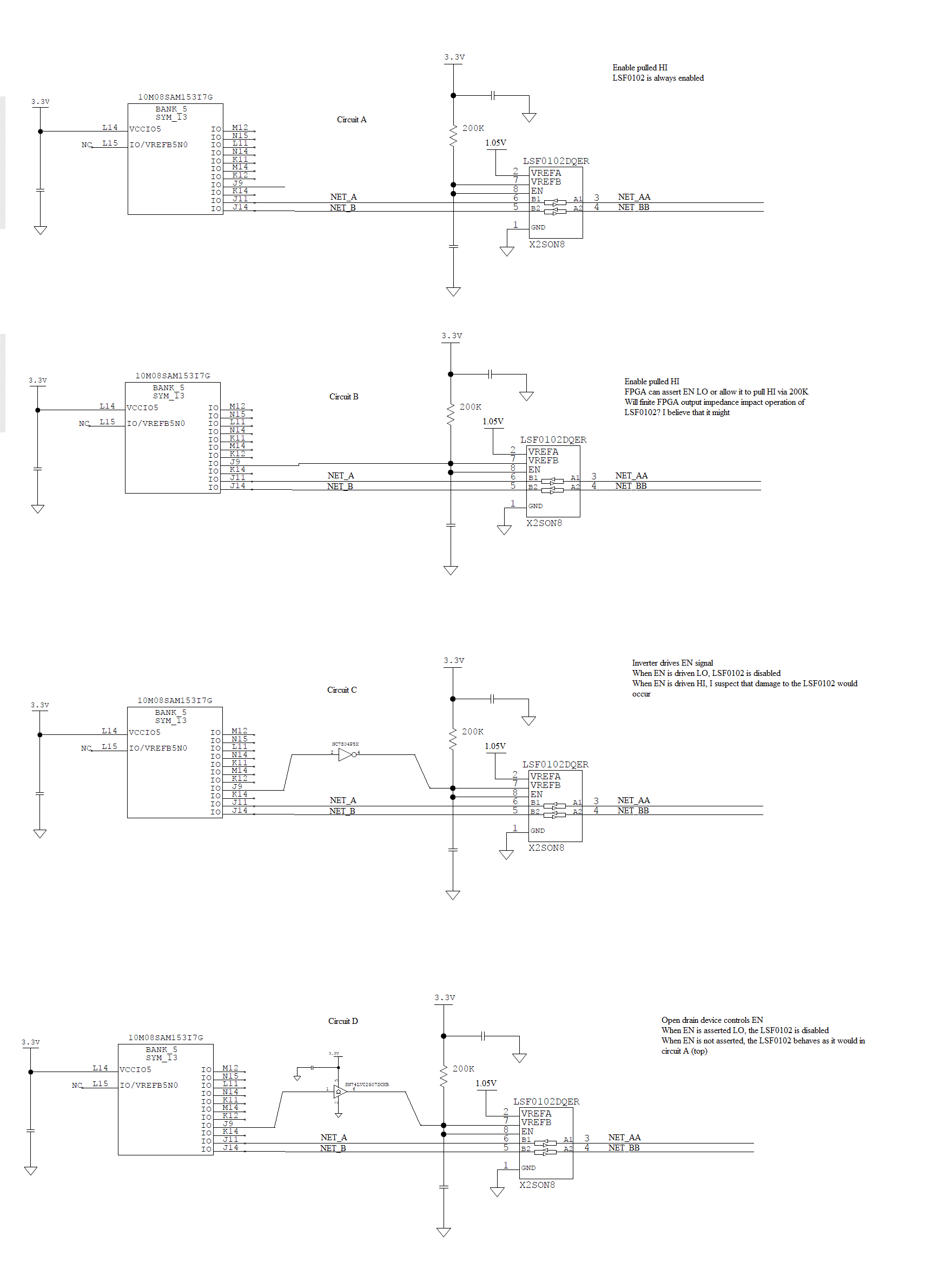
Do you have any guidance regarding active control of the EN signal? Specifically, the datasheet states that the EN needs to be connected to VREFB, and that pin pair then pulled to the relevant rail via a weak pullup, 200K Ohms nominal value. The datasheet also indicates that the EN signal, when driven LO, will disable the device. This leads me to believe that the EN signal should only be actively asserted by an open collector or similar driver. Is this correct?

I have two use cases which I believe are both bad.

The first case is where a push-pull driver actively drives the EN signal. I believe that a LSF0102DGEQ configured in this fashion would become damaged very quickly.

The second case is where an FPGA IO is used. The FPGA IO can assert the signal LO to disable the LSF0102DQEG device and then be tristated in order to allow the external 200K pullup to perform its function. I believe that in this scenario, the weak internal impedance of the FPGA IO would tend to interact with the LSF0102DQEG. FPGA IO impedances can vary widely from die to die, which would tend to lead to differing behavior between units.

Thanks.

  • See the application report Voltage-Level Translation With the LSF Family (SLVA675):

    Connecting the EN pin directly to Vref_B ensures that the voltage drop over the reference transistor's source/drain channel is the same as its threshold voltage.

    Driving the EN pin to some fixed voltage means that the gates of all transistors will have a different voltage, but for most voltages, the LSF will still work.

    What do you mean with "weak impedance"? No current is flowing into or out of the EN pin, so the impedance does not matter.


    What frequencies do you need? In general, the easiest way to design a circuit with a LSF is to replace it with a TXS.

  • Please see the attached image. I believe that Circuits A and D will operate correctly, while B and C will not.

  • Hi Brad,

    We have a great video training series that covers LSF operation, one video in particular addresses the EN pin. Please see below:

  • Without some pull-up resistors on the data lines, none of these circuits will work. But you are correct, the EN pin needs to be pulled low with an open-drain driver (as shown in the video).

    And I repeat my recommendation to use the TXS0102 instead.