This thread has been locked.

If you have a related question, please click the "Ask a related question" button in the top right corner. The newly created question will be automatically linked to this question.

Circuit recommendations for 8k2 comparator

Other Parts Discussed in Thread: CC1310

Hi,

I'm trying to develop an 8k2 comparator with a CC1310 Launchpad. I tried to monitor with the sensor controller studio and a voltage divider circuit but the consumption is too high(0.4-0.5mA).

My test circuit:
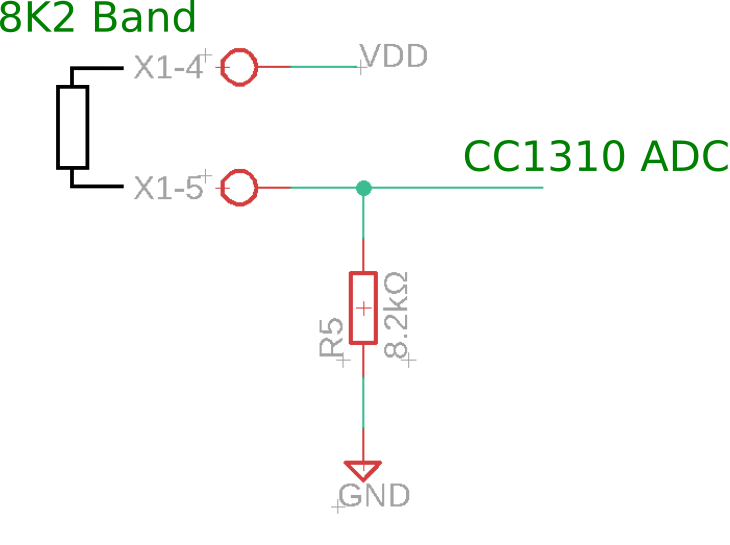
I'm thinking of using a comparator instead of the voltage divider.
I would like to have an opinion on what the best alternative is and if possible an example circuit to guide me since I do not have experience with comparators.

Best regards.

  • I have another question.
    The circuit has two more inputs, one is a NO and the other an NC. The CC1310 with the pull-up enabled have consumption of 277 µA when the input is connected to the GND. What is the best way to decrease this consumption too?


    Best regards.
  • Hi Renato,

    I'm not sure I fully understand what your use case is, could you elaborate on what you want to achieve?

    As for comparators, the COMPB resource might be what you seek which is the low-power comparator inside the device.
    As for pull-ups, they will consume current when ever they need to pull, so if you are seeing 277 uA this most likely mean that you are trying to pull the line high while someone is driving it low.
  • Hi M-W,

    The case is to know if between the x1-4 and x1-5 I have an 8.2k resistor, I tried with a voltage divider but that give a high consumption because even only read the pin a few times per second, the R5 is connected with the GND so it will consume all the time that the 8k2 resistor is connected.

    What is the best technique to use in this case?


    In the pull-ups I get this consumption(consumption give in the datasheet) when I take the line down, that's the problem, I can spend a lot of time down and a lot of time with the line high, so I need a solution that gives low consumption in both cases.

    Best regards.

  • Hi Renato,

    How fast do you need to react to this? Have you considered using a periodic ADC sampling? You could use the divider approach but with higher divider values in combination with ADC to estimate the resistance.

    Possible, you could even combine it with some interrupt functionality to allow you to react to the resistance being connected and then performing the ADC reading. You could then take it even a step further and grounding the lower part of the divider using an IO which means you can drive it in either direction (pulling it high after a reading to avoid leakage).
  • What is the use case for this circuit? Is the aim to detect if you have a 8.2 kohm resistor connected? Would you be able to do the same with measuring RC discharge and using the TDC to measure the discharge time or use the ISRC to give a known current and then measure the voltage. It depends some on which accuracy you need. You could also use switches to ensure that the resistor ladder is only on when doing the ADC conversion.
  • I did that yesterday and works fine. I power the ADC with another pin and only put high when I go read the ADC. The consumption goes below the 50uA with 20 samples per second.

    I don't find any solution yet to the NO and NC pins. I can remove the interrupt and read the pins like the ADC, but I liked to maintain the interrupts for those pins. What do you think?

    In the Sensor Controller Studio, I can enable the digital input pins with pull-up only when I want to read the value?

  • I tried this code for the NC and NO pins but the consumption is equal to the interrupt pull-up code.

    The gpioDisableInputBuf don't disable the pull-up.

    // Enable digital input pins
    gpioEnableInputBuf(cfg.pAuxioINoNcPins[0]);
    gpioEnableInputBuf(cfg.pAuxioINoNcPins[1]);
    
    // Sample digital pins
    gpioGetInputValue(cfg.pAuxioINoNcPins[0]; output.NO);
    gpioGetInputValue(cfg.pAuxioINoNcPins[1]; output.NC);
    
    // Disable digital input pins
    gpioDisableInputBuf(cfg.pAuxioINoNcPins[0]);
    gpioDisableInputBuf(cfg.pAuxioINoNcPins[1]);

  • Hi,

    This code decreases consumption but uses two more pins.

    // Use output pin LOW as GND
    gpioClearOutput(cfg.pAuxioOEnableAdc[1]);
    
    // Enable digital input pin NO with pull-up
    gpioEnableInputBuf(cfg.pAuxioINoNcPins[0]);
    
    // Get NO pin value
    gpioGetInputValue(cfg.pAuxioINoNcPins[0]; output.NO);
    
    // Disable digital input pin NO
    gpioDisableInputBuf(cfg.pAuxioINoNcPins[0]);
    
    // Set output to HIGH
    gpioSetOutput(cfg.pAuxioOEnableAdc[1]);

    Any idea for a solution that use interrupts?

  • As suggested by TER, you might want to look into using the TDC and measuring the discharge/charge time of a RC filter using the ISRC.
    As for what ever the idle state of the resistor bridge is, you would need to account for the leakage in several parts. For example, having the static resistor being 8.2K might not be the best choice as this implies a quite high current draw when putting 3.3V across it.