This thread has been locked.

If you have a related question, please click the "Ask a related question" button in the top right corner. The newly created question will be automatically linked to this question.

SN74LVC1G123: No Output Pulse

Part Number: SN74LVC1G123
Other Parts Discussed in Thread: ISO7810, STRIKE

Hi,

I'm currently having a problem using SN74LVC1G123 -- the output pulse isn't appearing. An image of it in my schematic can be seen below. I would like it to trigger on the falling edge of input A and output a pulse that is a little over 10 us long (I think the application curves place it at roughly 20 us, which is fine).

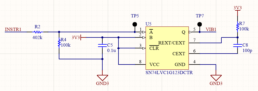
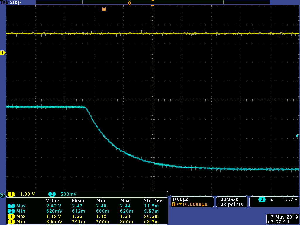
The "3.3 V" power supply is currently at a little under 3.6 V. The input, measured at TP5, is shown below on the yellow trace (sorry about the phone picture, didn't have a flash drive on me at the time). In both pictures below, the blue trace is the signal INSTR1, which is divided down by 1/4 (R2 has been changed to 301kOhm).

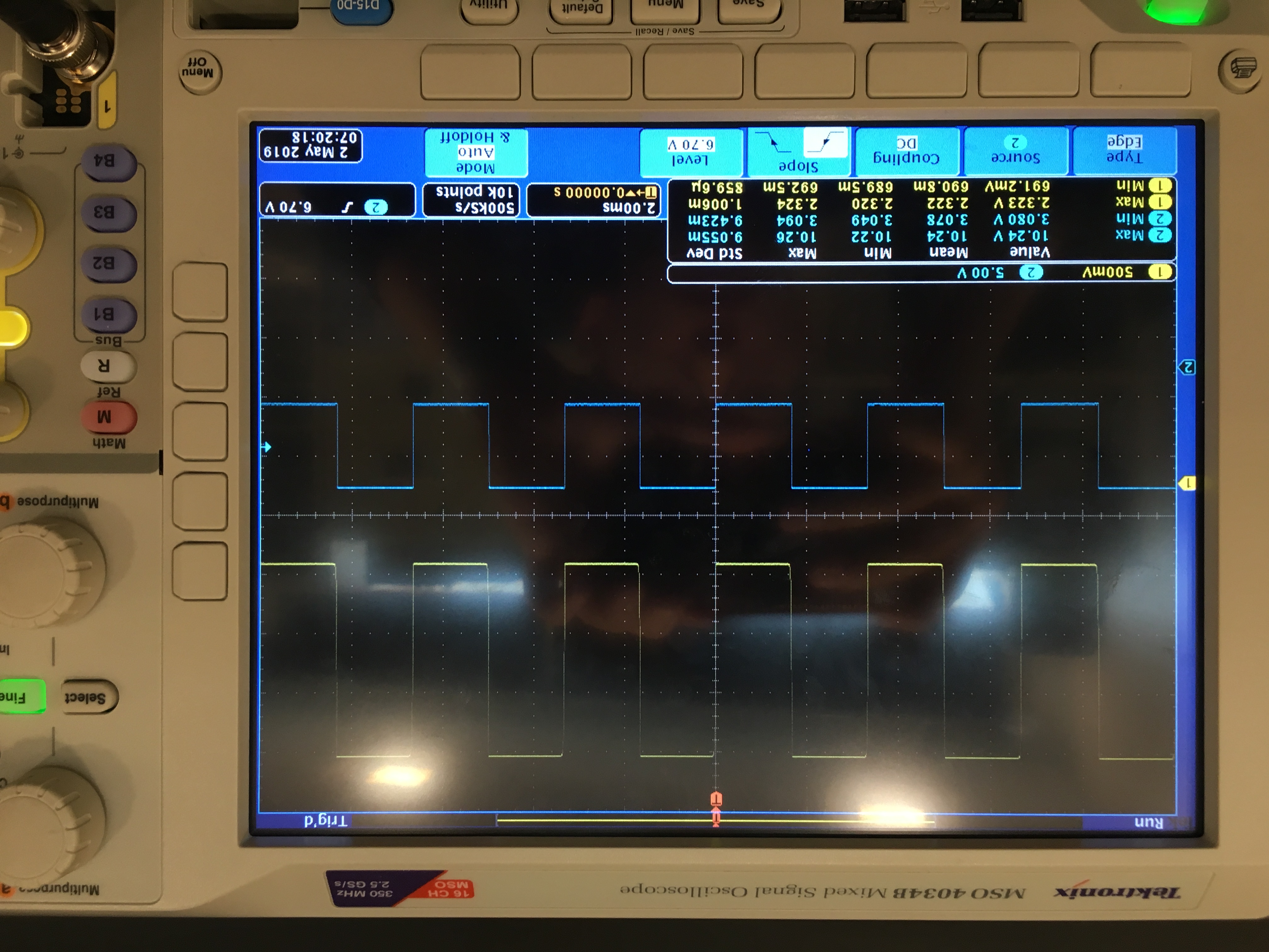
Based on the datasheet, I'm led to believe that this should work fine. The max of the input is 2.3 V (above 2 V), and the min is ~700 mV (below 800 mV). The output, measured at TP7, is shown below.

The output, for whatever reason, is at a DC ~1 V. Can anyone let me know if there's something I'm doing wrong? If more information from my end is needed, let me know and I would be happy to oblige.

Regards,

Michael

  • Hi Michael,
    It looks to me like your schematic is correct for producing ~10us pulses at every incoming falling edge. My initial thoughts are that it's very odd to see 1V at the output -- this indicates a circuit problem to me, since the output should be actively driving either 0V or VDD (~3.6V). Is it possible that there is an error in the wiring of the device? Or perhaps there's something else driving the line?

    I'd double check the pinout, orientation, and look for any solder bridges or other circuit problems, especially around pins 5 and 7.

    You can also monitor the voltage on pin 7 to see if the capacitor is being discharged correctly with each falling edge -- this device operates by discharging the capacitor when there is a trigger, then monitoring the recharge to get the timing of the output pulse.
  • Hi Emrys,

    Thanks for the response. I just went through and checked to see if any of the pins were unintentionally shorted together. The only pins that are connected are pins 4 (GND) and 6 (Cext), which, based off of Fig. 1 in the datasheet, seems correct.

    As far as orientation goes, I'm orienting the chip using the gray bar marking on the chip to indicate pin 1. And I don't think anything else could be driving the line -- the output is only being connected to two things: pin 3 of the MAX4648 (input of an analog switch) and pin 4 of the ISO7810 (input of digital isolator).

    I will try to monitor pin 7 and see what the voltage looks like in my application.

    Is there anything else that you can think of that might be the problem? Is there a chance that the IC needs replacing?

    Regards,
    Michael

  • There's always a chance that there was an ESD strike to the device that would cause abnormal behavior -- one of my first troubleshooting steps would be to swap the IC just to be sure.
  • Thanks, I think I'll try this next. I'm going to also try and test the chip outside of my system on a breadboard of sorts to see if I can get it to function properly in an isolated environment.

    For the sake of completeness, below is an image again of the output of the multivibrator (yellow) and input (blue), this time zoomed in significantly on the time axis. The falling time of the input isn't too slow or anything for the multivibrator, right? It only needs to cross the low logic level?

  • The slow input signal is OK for this device since it has Schmitt-trigger inputs.
  • Hi Emrys,

    Thanks for all of your help so far, it's been really helpful. Over the past day, these are the steps that I've taken in debugging:

    1. I tested and verified an extra SN74LVC1G123 on a breakout board placed on a breadboard. I was able to successfully generate the pulse with the duration that I was looking for (~10 us).
    2. I then took the old multivibrator off of the PCB and placed it on a breakout board in the same setup to see if maybe it had been destroyed by ESD or something, but it turns out that it was working fine. Without the chip on the board, I realized that pin 5 was being regulated to about 1.4 V for some reason, so I wanted to see why that might be the case, since I was previously seeing ~1 V at the output of the multivibrator (thinking that the two may be related).
    3. I took an extra ISO7810 and placed that in a breadboard setup and learned that, powered on with no input, the 1-side input goes 1.4 V, but operates fine when an input is applied from a function generator. This then made me think that maybe, for whatever reason, SN74LVC1G123 and ISO7810 are just incompatible (maybe SN74LVC1G123 didn't have enough drive strength?).
    4. On the breadboard, I connected both SN74LVC1G123 and ISO7810 in the same way as it is in my system, and it works perfectly fine, see below (yellow is the output of the multivibrator, blue is the output of ISO7810).

    This may be beyond the scope of how much you can help me, but I've attached my schematic below. I'm curious to see what else you think could be the source of my problems. Below is a small snippet of my layout showing the only places in which the output of the multivibrator (U5 on the left) is connected (pin 3 of MAX4648, U3, and pin 4 of ISO7810, U8).

    sense_mini v2.2.pdf

  • I doubt the input current from the ISO7810 would be a problem for the SN74LVC1G123 -- the LVC family of devices can drive quite a bit of current -- well beyond what the datasheet lists. I wouldn't recommend doing this - but I've seen them sink over 250mA before.

    Looking into the ISO7810 datasheet I found that it has this protection structure on the input:

    Since you have a lot of different grounds running around the board, I was wondering if the ground might have a DC offset that's causing your headaches.  If that were the case, one of these diodes could be clamping the output to a higher voltage than expected. It could happen from the positive supply as well, but I think that's probably less likely.

    You might try opening a new thread using the ISO7810 part number to see why the device might be clamping the input to 1.4V. I'm sure the apps engineers on their team know much more about that part than I do.

  • Thanks for all of your help Emrys, I'll look into creating a new thread.