Dear,
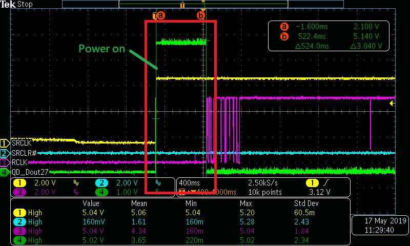
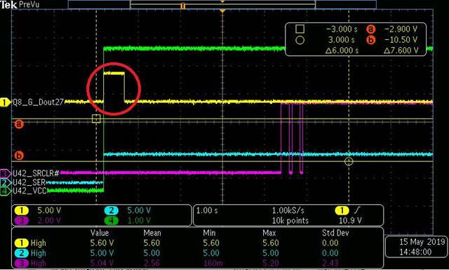
we use SN74HC595DR, but we find, if power on and SRCLR pin was pull low, why output wavform have one puls? is normal?
measurement waveform as below chart:
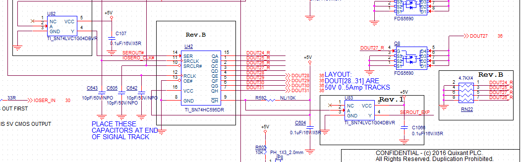
schematic:
If any suggestion, Please advise me.
Thanks,
Best regards,
Lawrence.
Dear,
we use SN74HC595DR, but we find, if power on and SRCLR pin was pull low, why output wavform have one puls? is normal?
measurement waveform as below chart:
schematic:
If any suggestion, Please advise me.
Thanks,
Best regards,
Lawrence.