This thread has been locked.

If you have a related question, please click the "Ask a related question" button in the top right corner. The newly created question will be automatically linked to this question.

SN74HC14: device gets damaged in a digital I/O module

Part Number: SN74HC14

Hello,

my customer is currently facing an issue with the SN74HC14 device on a digital I/O mdoule that has been in production already for close to ten years. In the last few months they have had 15 boards return from the field. The HC14’s doesn't give on output the correct voltage level inverted of the input voltage level. 

In some boards the input of HC14 is “cut” at about 2 volts, so the engineer thinks that the input is damaged . They don’t know why and this issue is not observed in I/O modules with HC14 of different manufacturers.

attached are a couple of scope shots sent by the customer. I can also share the schematic of the design via Email: 

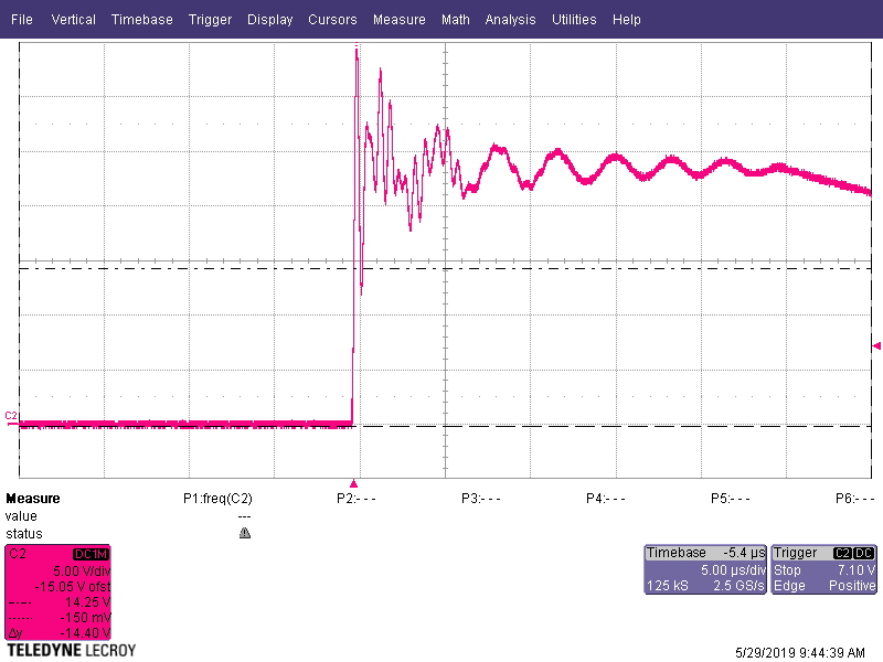
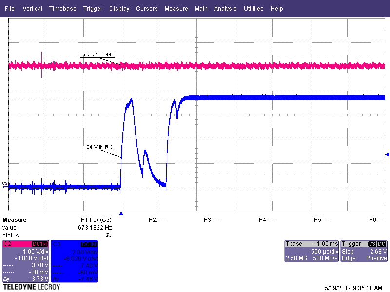
  • Images A),B),C)   signal of board ok       in HC14 high level  = about 5,6V (diode internal protection used)
  • Image D) not mounted HC14 to see the level of in HC14 ( no protection diode of HC14 ); Voltage level = about 7,40 V
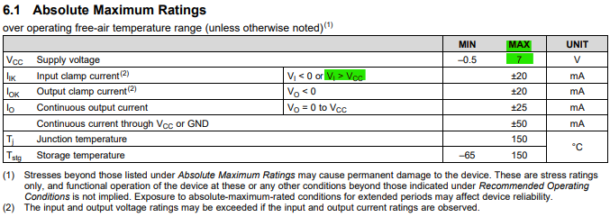
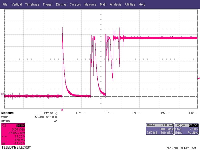
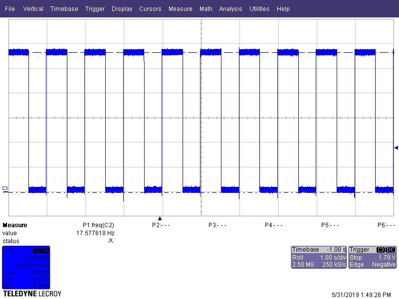
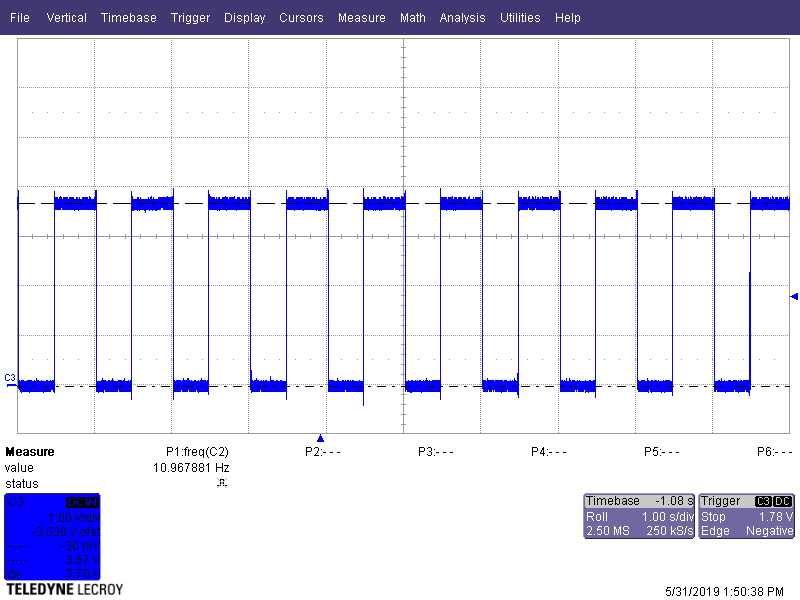
  • Image E) in HC14 with on/off cycle on input M25 ( square wave 0 – 24V )
  • image F) in HC14 “damaged” with on/off cycle on input M25 ( square wave 0 – 24V )

I hope this information helps to understand what is happening. Should you have further questions please let me know.

Best regards,

Stani


  • Hi Stani,
    From the above scope shots, I can't really tell what's going on. Can you provide just 2 scope shots -- one with the "good" input and output of the HC14, and one with the "bad" input and output of the HC14?

    Also, it would be very helpful if I can see a schematic. I have no idea where these signals are being applied to the device.
  • Hi Emrys,

    i'll send you the schematic as well as the detailed pictures via email.

    regards,

    Stani

  • Hi Stani,

    I have looked through all the images and the schematic you sent - thanks, those were very helpful.

    I noticed that the input to the SN74HC14, when the device is removed, is larger than the absolute maximum supply voltage rating of 7V. This can cause damage to the device, especially with transient events.


    I wanted to highlight here that the input voltage can exceed the supply voltage, however the voltage applied to the device should never exceed 7V (the maximum supply value).  This exception is intended to mean that if the supply is 3.3V, then the input can be 5V (or up to 7V max) as long as the current is properly limited (which it is in this case). It does not mean that the input voltage is unlimited -- ie you can't just apply 8V to this 7V max part and expect it to limit the voltage with no possibility of damage.

    Even very short times at higher voltage can cause damage to the gate oxide in the device. Since the manufacturing process shifts slightly over time and sites, failures beyond abs max are hard to predict. It sounds like they got lucky for a long time using these devices beyond their rated maximum voltage.

    I would recommend swapping the resistor values on their filter to ensure the voltage stays closer to 5V to prevent damage to the devices in the future.