This thread has been locked.

If you have a related question, please click the "Ask a related question" button in the top right corner. The newly created question will be automatically linked to this question.

TXB0104: Significant apparent crosstalk on output

Part Number: TXB0104
Other Parts Discussed in Thread: SN74LV4T125

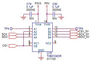
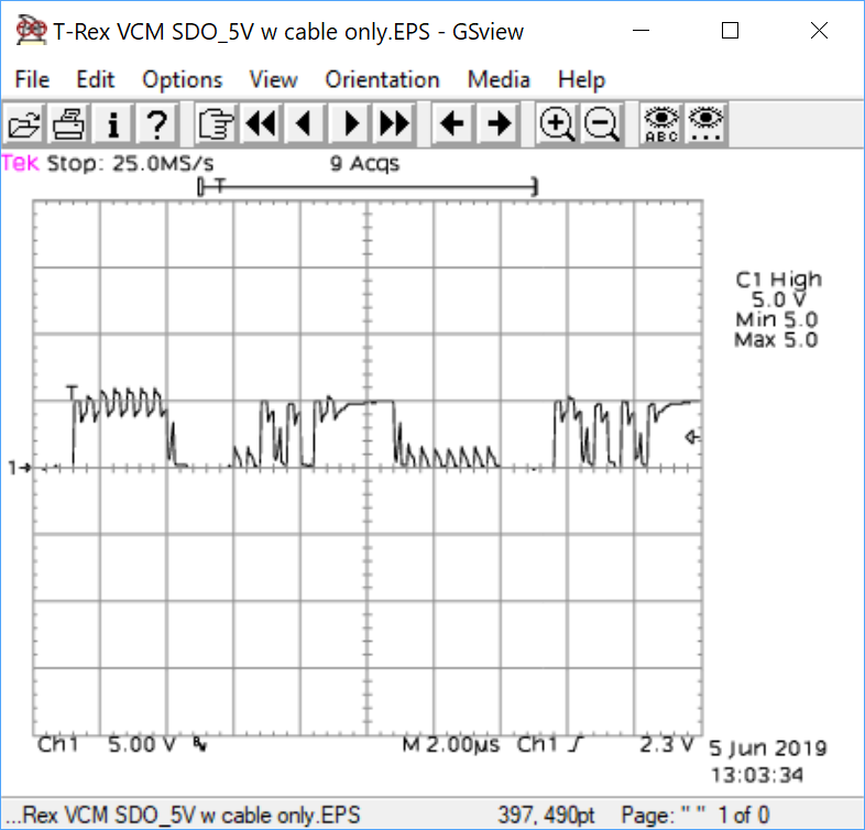
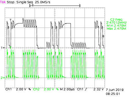
  When using TXB0104 to level shift 2.5MHz SPI from 3.3V to 5V, the 5V (See attached) output appears to have significant clock-to-data crosstalk, effectively corrupting the output, w/ only an unterminated 21" "zip" cable as a load. (Also see attached.) No improvement with the real load (SPI-controlled LEDs) connected.

  The 3.3V inputs are from a Microchip DSPIC33EP128MC506, and are clean.

  This was originally posted to tech support as case CS0034489, & they referred me here.

  • Hey Steve,

    I'll be happy to help with this issue. Could you provide a scope shot of both signals (SDO and CLK). Also are you able to remove the cable all the way to completely isolate the device from anything downstream?

  • This looks as if noise from the clock line affects the data line, and that the resulting voltage spikes are large enough to trigger the TXB's edge accelerators. I also suspect that the capacitance of the cable (and its connectors) is larger than the allowed 70 pF, which can lead to ringing.

    It might be a better idea to use a unidirectional translator with low-impedance outputs, e.g., SN74LV4T125.

  • Dylan,

      A scope capture of both clock & data should appear below, followed by another showing cleaner signals when the cable is disconnected. There's an intermediate connection in the cable at 7.5" from the PCB edge, & when that's disconnected the signal improves somewhat. It's a rough lab-only cable (also shown below).

  • Clemens,

      Thanks for the reply. The equipment we have on hand may not be capable of measuring down to 70pF, but I can investigate the SN74LV4T125 for a future board spin.

      Steve K.

  • Clemens & Dtlan,

      I found an LCR meter capable of measuring low capacitance, & it shows the capacitance of the 21" cable at about 20pF at 10KHz (the highest frequency of which the meter is capable).

      Steve K.

  • I estimate the time constant of those round curves to be about 500 ns; with the TXB's output impedance of 4 kΩ, the capacitance would be about 125 pF.

    In any case, the the problem is not the capacitance, but the crosstalk. On a PCB, I would recommend a ground trace between the two signals. A cable is more difficult; try two twisted pairs, clock+ground and data+power.