This thread has been locked.

If you have a related question, please click the "Ask a related question" button in the top right corner. The newly created question will be automatically linked to this question.

SN74LVC14A: About Partial-Power-Down Mode

Part Number: SN74LVC14A

Hi,

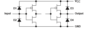
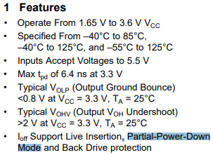
Could you tell me about SN74LVC14A Ioff and Partial-Power-Down Mode?
Please tell me the Ioff spec of this device.

Customer pull up the data output pin at 3.3V and 10kohm when Vcc = 0V.
In that case, leakage current occurs in the buffer Power.
And 700mV is observed.

1.Is there a condition that partial power down does not work?

2.Please tell me how to avoid leakage current and voltage.

3.When the pull-up resistor was 100kohm, it could be saved to 200mV.
   Is there a problem?

Best Regards,
Yusuke

  • Hi Tsukui,

    Gabriel would get back on this one, but it looks like there is no Ioff protection on this device.

    There is Ioff on the LVC1G/2G/3G devices though.

  • Hello,

    Please look at this FAQ on Ioff and partial power down for more information on that. As Shreyas mentioned, this device does not have the Ioff circuitry required for partial power down mode, since the specification for Ioff is not in the datasheet. Turning off the pull-up supply when VCC is 0V would avoid major current leakage.  If 0.7 V and 0.2 V is being measured at the output pin, the power ESD diode on the output is likely conducting and causing the voltage drops being observed. 

    thanks,

    Gabriel

  • Gabriel-san, Rao-san,

    Thank you for your comment and support.
    Let me confirm to make sure this issue.
    The description of Features in the data sheet is incorrect.
    Is my understanding of this correct?
    And If so, please tell me what will be fixed.


    And Please give your advice on the following questions.

    "2.Please tell me how to avoid leakage current and voltage.

    3.When the pull-up resistor was 100kohm, it could be saved to 200mV.
       Is there a problem?"

    Best Regards,
    Yusuke

  • Yusuke,

    Yes there is an error in the datasheet, this device does not support partial power down. It has been reported and we will correct it. The small current through the pull up resistor should not damage the device while VCC is 0V, but to further assess and debug the issue, I need more information about the device setup and your measurements. Could you please show me where the 200 mV is being measured and the schematic around the device if it is available? How many outputs are being used and have pull up resistors? Do you know if there is a specific reason that the pull up is active while the VCC pin is 0V?

    thanks,

    Gabriel

  • Gabriel-san,

    Thank you for your kind support.

    >Could you please show me where the 200 mV is being measured and the schematic around the device if it is available?
    >How many outputs are being used and have pull up resistors?
    200 mV was measured at the Vcc pin. 
    Pull up resistors is 100kohm. Pull up voltage is 3.3V.

    >Do you know if there is a specific reason that the pull up is 0V?
    Yes. 3.3V is biased to OUT pin before power-on of SN74LVC14. The time to be biased is 400msec.

    Customer tried 10 kohm. After that I try 100 kohm.
    (10kohm: 700mV, 100kohm:200mV)

     For example, 3.3V/10kΩ=0.33mA.
    This is within the absolute maximum rated current range.
    Is it possible to destroy it?


    Customers are afraid of device destruction.
    Could you give me your advice? 


    Best Regards,
    Yusuke

  • Yusuke,

    This current is small enough that it will not damage the device. The current will flow through a parasitic diode in the output circuitry and out of the VCC pin. As long as the VCC supply can take the 0.33mA, then using either pull up resistor is fine. 

    regards,

    Gabriel