This thread has been locked.

If you have a related question, please click the "Ask a related question" button in the top right corner. The newly created question will be automatically linked to this question.

SN74AUC1G14-EP: How to replicate positive going input threshold?

Part Number: SN74AUC1G14-EP

Hi TI expert,

My question is related to this one: https://e2e.ti.com/support/logic/f/151/t/814578?tisearch=e2e-sitesearch&keymatch=SN74AUC1G14

For SN74AUC1G14-EP, I'm verifying the Positive and Negative going input thresholds. I tried to replicate the positive going input threshold for Vcc=1.65V condition, using a triangle wave at the input, and drawing maximum of 8mA at the output, however I saw VT+ was slightly below the VT+ min on the datasheet. From what I understand, this should not be happening.

What is the recommended current draw at the output when testing this characteristic?

Thank you

Shirley

  • The input threshold should be completely independent from the output current (this is why the current is not listed as a test condition in the datasheet).

    How much is "slightly"? What is the accuracy of the 1.65 V supply? (If you're using a nominal 1.65 V supply, it might be possible that the actual value is slightly below that. But that should not happen if you're using a lab power supply.)

  • I agree with Clemens, in that the output is independent of the input.

    With the potential exception of GND bounce or VCC droop from high inductance VCC or GND connections and/or poor decoupling.

    Can you post scope shots of the test?  Include VCC probed on the pin of the device if possible.  Use the paper clip icon to attach.

    Regards,

    Wade

  • Hi Wade and Clemens,

    I believe you're right, the Vcc was slightly below 1.65V which presented with a positive going input voltage below the minimum on the datasheet.

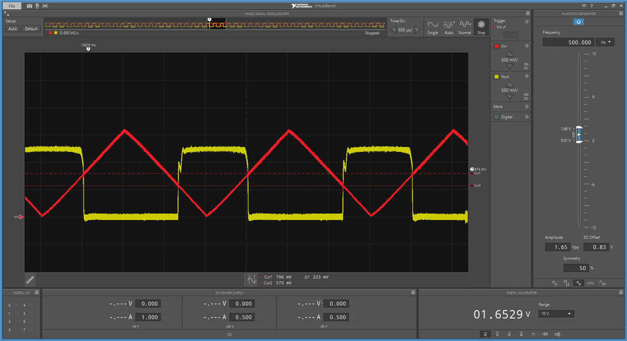
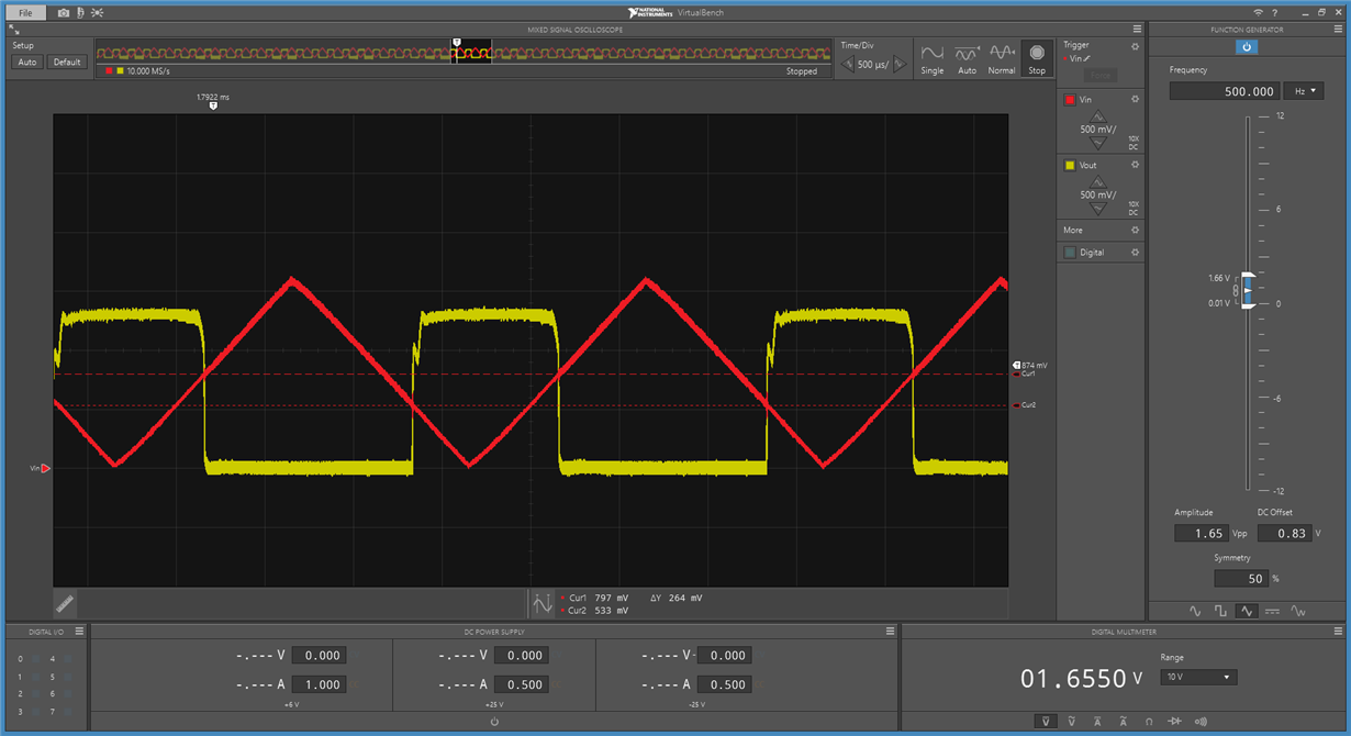
    The resulting scope screenshots are attached for those samples that were previously failing. They're slightly above the minimum 790mV now

    Thanks for your help

    Shirley