This thread has been locked.

If you have a related question, please click the "Ask a related question" button in the top right corner. The newly created question will be automatically linked to this question.

SN74AUC74: SN74AUC74 draws high current when inputs biased

Part Number: SN74AUC74

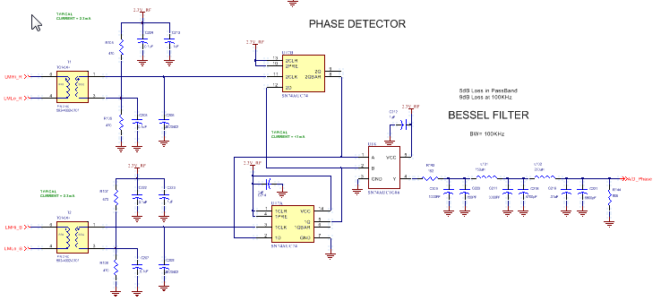
I'm using an SN74AUC74 and SN74AUC86 in combination for a phase detector (see below). The chip driving the SN74AUC74 has differential outputs swinging approximately 1.25V. I've used a biased balun to convert the differential output to single-ended input. However, the biasing appears to be causing a latch-up in the SN74AUC74 since the current draw from the device is >30mA. Presumably, I need to add a resistor or diode, or ensure the device starts up in preset/clear. What do you recommend?

  • Logic signals are supposed to be at or near the rails. If not, both input transistors are activated, and you get cross currents.

    And while the schematic has too low a resolution to be readable, I suspect that the capacitors on the inputs make the signal edges slower than the allowed 20 ns/V.

    See [FAQ] How does a slow or floating input affect a CMOS device?

    To handle analog signals, put a comparator in front of the logic gate.

  • Hi Donna,

    Could I get some scope shots of the clock inputs and d inputs of the SN74AUC74 device?

  • Clemens,

    Thanks for the reply. The caps on the clock inputs are actually not placed at this time.

    This topology was used in a previous system with an SN74LVC74 instead of the SN74AUC74. The SN74LVC74 does not draw more than 5mA, even in standby (i.e no clock input). Why is the SN74AUC74 different?

  • Other logic families specify a value for ΔICC, but not AUC. This might indicate that handling of non-digital signals was never a design consideration for AUC. Furthermore, support of low supply voltages requires that the transistors have a very low threshold voltage, so this would explain the higher cross currents.

    I suspect that these single-ended signals were outside the recommended operating conditions (VIL, VIH, Δt/Δv) even for the LVC devices.

    I repeat the recommendation to use comparators. (These might be able to replace the baluns.)