Because of the holidays, TI E2E™ design support forum responses will be delayed from Dec. 25 through Jan. 2. Thank you for your patience.

This thread has been locked.

If you have a related question, please click the "Ask a related question" button in the top right corner. The newly created question will be automatically linked to this question.

SN74LV123A: SN74LV123A Triggering on both rising and falling edges

Part Number: SN74LV123A

Hello TI Forum,

I am trying to trigger the SN74LV123A on the rising and falling edge of the same signal.

For this I have shorted both inputs (inv&non-inv) of the same channel.

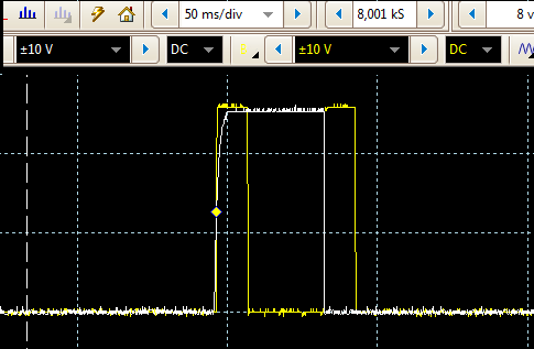
I works fine on ChA (white input to P1&P2), yellow = output P13)

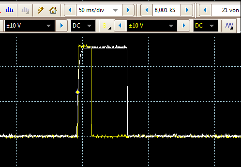
As for Ch B it doesn´t trigger on the falling edge (white input to P9&P10), yellow = output P5)

Am I missing something ?
I tried swapping components, signal source (2 ch rotary encoder), different IC´s etc but nothing works.

Could it be the IC is not designed to work in this mode? Why would it work on Ch A but not Ch B?

Seriously considering two IC´s using Ch A on both but should be wasted PCB space etc...

I hope someone can help :)

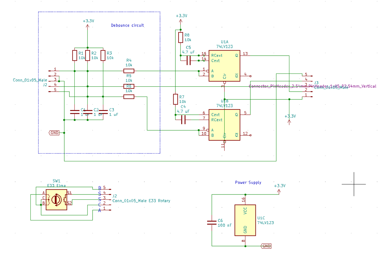
Circuit is as follows:

  • Hi,

    The very first thing I notice in your schematic is that the ext capacitor is in the wrong place on Channel B. It goes on pin 6 and you have placed it on pin 7. I don't believe pins 6 and 7 are shorted internally to ground or to each other, you need to move that capacitor.

    Secondly if this doesn't solve your problem, are you doing these tests independently? I mean, power up and test only channel B. Then power up and test only channel A? Are the traces of both the channels the same?

    Thanks!

    -Karan

  • Hi Karan,

    Thanks for your comments, You´re right I´ve drawn the resistor to the wrong pin! I checked my circuit and it was wired to the P7 after all, but at least the schematic is correct now.

    I´ve done some more testing with only channel B connected (Ch A disabled by P1+3 to high, P2 low, I´ve left 14+15 open). It does trigger correctly only when either rising or falling edge input is used (other input to H or L resp.).

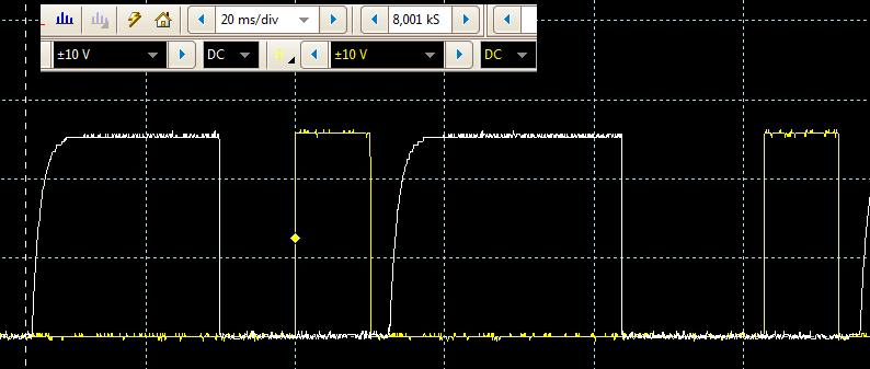
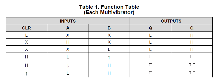
    But it won´t work with the input connected to both B and Ā:

    All I get now is either none or a very late phantom trigger.

    I can only assume it has to do with the internal wiring of the IC. After all if, as per functions table, B only triggers when Ā is low and Ā triggers when B is high, maybe on Ch2 Ā no longer registers as low when the signal rises on B and B no longer registers high when if falls on Ā.

    This behaviour seems reversed on Ch 1 which would make it work.

    I hope my reasoning makes any sense?

    KR

    David

  • Hi David,

    Your reasoning is correct. Even I don't know everything about the internal circuitry. But there seems to be a longer delays on certain pins which might change on the batch of parts you might order. I would not trust your channel A working on this part specifically as it might not work on another sample of the part.

    If you look at the application and implementation section 10 of the datasheet. We have a example setup for detecting both a rising and falling edge of the same signal. It recommends using both channels with one channel for rising and the other channel for falling edge detect for this reason.

    Thanks!

    -Karan

  • Hi Karan,

    Its a shame but I agree with you. Maybe I was too optimistic on using both inputs on the same channel from the same source.

    I´ll now use two IC´s with the example circuit which seems to work ok but will have to go for the VQFN package to minimize pcs space.

    Thanks anyway

    David