This thread has been locked.
If you have a related question, please click the "Ask a related question" button in the top right corner. The newly created question will be automatically linked to this question.
Dears
Thanks for your help ,
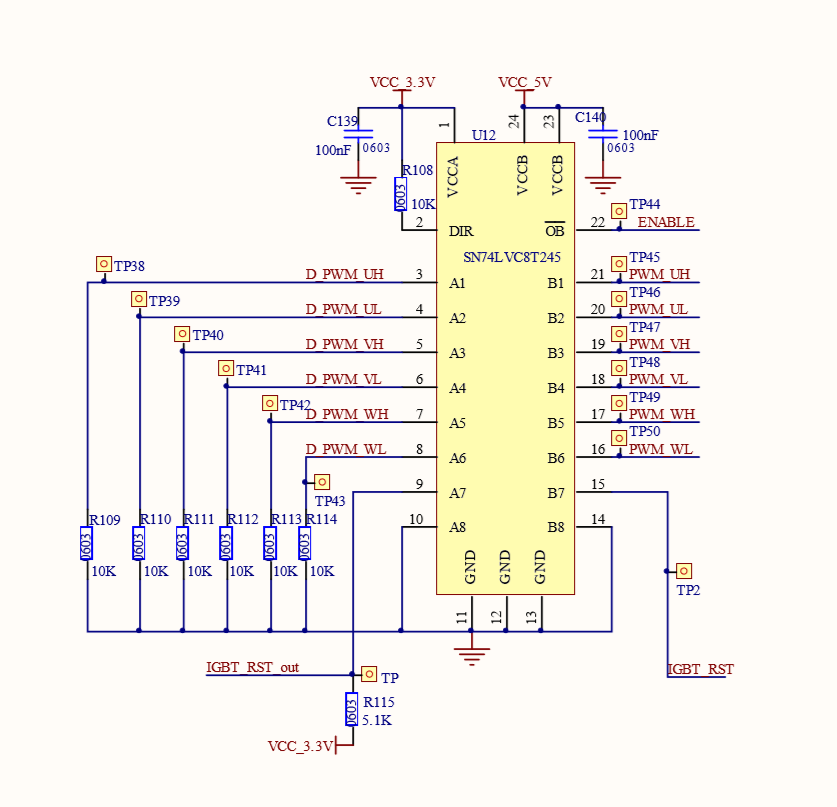
the OE PIN is high ,5V.
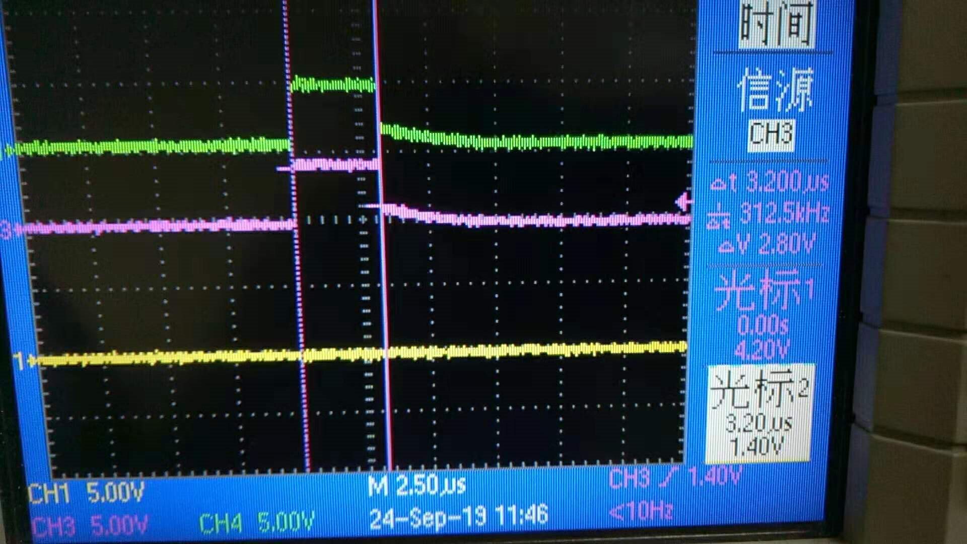
the wave : red is output pin B5 ,the green is output Pin B6 ,
What is the yellow channel?
How is the ENABLE signal controlled? Can you show waveforms of ENABLE and VCCB?
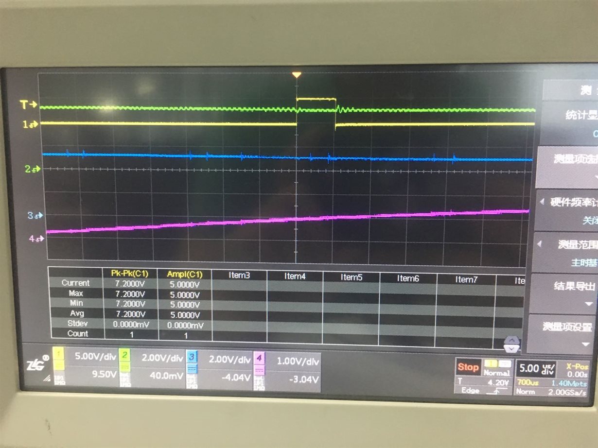
the channel1 is B5 ; the channel 2 is VCCB ; the channel3 is Enable ; the channel 4 is VCCA.
Hi,
The architecture of direction controlled level shifters can cause the device to glitch during power-up. It has to do with how and when the control circuitry gets powered. The direction circuitry switch a certain port to an output can cause this pulse.
Are you able to power the VCCA side before the VCCB?