This thread has been locked.

If you have a related question, please click the "Ask a related question" button in the top right corner. The newly created question will be automatically linked to this question.

SN74LVC1T45: Level translator cutsom board not providing desired output after 2Mhz

Part Number: SN74LVC1T45

Hello Team,

I am using SN74LVC1T45 for level translation from1.8V to 5V. I have designed a custom board for this. The problem I am facing here is that I am getting desired out from 10Hz to 2Mhz but from 3Mhz the shape of the output waveform is somewhat odd or in irregular shape when compared to an actual square wave.

I am attaching the schematic I have followed and the output waveform at 1Mhz and 4Mhz.

I am feeding 1.8Vpp from signal generator and measuring output using high impedance probes.

Please help with this.

Thanks In Advance

Schematic

1Mhz

4Mhz

  • Hi,

    What load are you driving with this device? Is there a long transmission line? A large load can cause the frequency of operation to decrease as you see in your case.

    Thanks!

    -Karan

  • Your input trace shows a bipolar signal:

    If your signal generator can supply more than 50 mA, then it is likely that the negative voltage has already damaged the device.

    Configure the signal generator for unipolar output (0 V to 1.8 V), and try again, ideally with a new chip.

  • I made the output from the signal generator as unipolar and tested the board. The following are the snapshots of the same.

    1MHZ Input signal from Signal Generator


    1MHZ Output signal

    4MHZ Input signal from Signal Generator

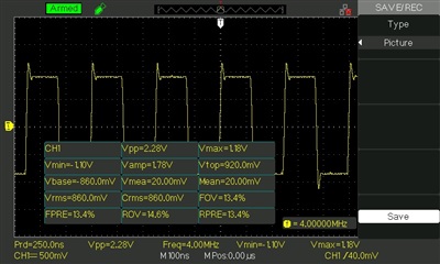
    4MHZ Output signal

  • Hi,

    The only problem I see now are the overshoot and undershoot on the device. Do you have a load connected to the output?

    Will your system be fine with this amount of overshoot and undershoot?

    Thanks!

    -Karan

  • Thank you for your reply.

    I need to avoid those overshoots and undershoots as much as possible. Right now I have just connected the output to the scope.

    Minimal overshoots and undershoots are fine but at higher frequencies, the output waveform is not a square wave.

  • Hi,

    To avoid overshoot and undershoot, you would need to add damping resistors to the outputs. This will slow down your rise and fall times further making your signals not "square waves". The reason you have overshoot and undershoot is because the LVC device has a high drive strength. If you have a load that this device is supposed to be driving, then the overshoot and undershoot will attenuate.

    What are you driving with this device? Why do you need it to be an exact square wave?

    I see your output in your last response at 4 MHz and it looks very much a square wave to me. What is the highest frequency you want to use this device at?

    Thanks!

    -Karan

  • Sorry for the late reply. I changed the damping resistor value to 150R from 100R and output is as desired