This thread has been locked.

If you have a related question, please click the "Ask a related question" button in the top right corner. The newly created question will be automatically linked to this question.

SN74HC14: Schmitt Trigger to cleanup digital signal

Part Number: SN74HC14
Other Parts Discussed in Thread: LM324, LM397, TLV7031, TLV7011

Hello,

I have pasted an image of a digital signal from my oscilloscope below.  The yellow is a digital signal that has been transmitted down a long transmission line and needs cleaned up.  The blue is my attempt to run the yellow signal through the SN74HC14 Schmitt trigger to clean the signal up.  You can see that a Schmitt trigger will not work for this type of signal since its based on a fixed threshold voltage.  Some of the "peaks" of the signals are lower than the "valleys" of other signals because the signal itself is oscillating so a fixed voltage threshold method of cleaning the signal up will not work.

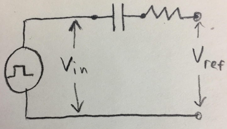
My next plan of attach is to use a differentiating op amp to measure the slope of the signal. I will then use the LM324 comparator to decide if the slope of the line should be HIGH or LOW. If the signal is positive from the differentiating op amp (above zero), the LM324 will output HIGH.  If the signal is negative from the diff op amp, the LM324 will output LOW. It will act as a variable Schmitt trigger in a sense and won't care if the signal itself is 'wavy".

Before I order more parts, does this logic makes sense?  Is there a TI semiconductor that can measure the slope of a signal and output HIGH or LOW based on the slope?   Basically just checking if there is an easier way to do this before I go ahead with my plan, and not re-invent the wheel if there is an easier way. Thanks so much for the help.

  • A differentiator will be able to detect the slope.

    But detecting whether the signal is above or below the short-term average is possible with a single comparator. To create the reference voltage for the comparator, run the signal through a low-pass filter (a simple RC should suffice).

    And I'd recommend to replace the LM324 with an actual comparator.

  • Do you have a recommended comparator I should use? IE LM397 (single general purpose voltage comparator)?

    For the low pass circuit, I would hook the resistor-capacitor up in series I assume to slow the digital signal down for my Vref value?

    Thanks for the help.

  • A comparator's input impedance is approximately infinite, so no current would flow. For a low-pass filter, the capacitor should shunt high frequencies to ground:

    It looks as if you have a 3.3 V supply, so you need a low-voltage comparator with rail-to-rail inputs. The propagation delay should be below 5 µs. To save components, let's choose built-in hysteresis and a push-pull output. The search function points to the TLV7011 or TLV7031.

  • Thank you very much. I will order the parts and try it out. 

  • Hello,

    I just wanted to share some feedback from this project.  I experimented with the circuit you provided above and it worked perfectly. The transmission signal is 115,200 bps down 2000 meters of cable. On the receiving end, I used the TLV7011 as the comparator, 47 ohms for my resistor and 0.047 uf for my capacitor.  3.3 volts for my power. Couldn't ask for a better result. Thanks!