This thread has been locked.

If you have a related question, please click the "Ask a related question" button in the top right corner. The newly created question will be automatically linked to this question.

SN74ALVC164245: Insulation coordination according to the standard EN 50124-1

Part Number: SN74ALVC164245
Other Parts Discussed in Thread: SN74LVCC4245A-EP,

Dear Engineers,

In ours control system we're trying to approve according to the standard EN 50124-1 (Railway applications - Insulation coordination).

Minimum creepage distances (based on rated insulation voltage up to 50V) between channels is 0,025mm inside component.

What are the minimum distances between channels in the inside components SN74ALVC164245 and SN74LVCC4245A-EP?

Thanks,

Michal Matějka

  • All inputs and output share the same ground, and are connected to GND and their VCC through ESD protection diodes. Voltages differences of 50 V (anywhere) exceed the absolute maximum ratings and will damage the device.

    For your purposes, standard logic devices have a creepage distance of zero.

    If you need isolation, you need to use an isolator.

  • Thanks,

    but it means physicaly distance between channels each other in the inside component, which must be greater than 0.025mm (regarding EN 50124-1).

     I attached a picture for clarification.

    michal

  • Does a chip count as "printed wiring material"?

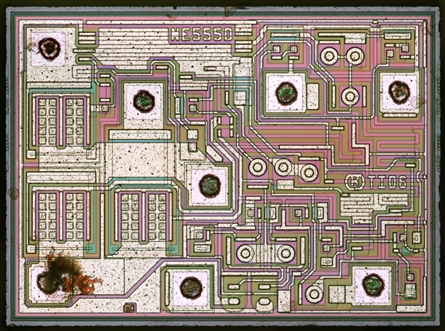
    Anyway, ALVC is fabricated with a 0.6 µm process, and TI does not guarantee the die layout. The distances are designed only for voltages inside the absolute maximum ratings, and are very likely much smaller than 250 µm.


    (source: Zeptobars)

  • Hi Michal,

    As Clemens has mentioned, if this part is exposed to 50V anywhere, it will get damaged.

    Secondly, it is unreasonable to expect modern silicon devices to have bond wires that are less than 0.025mm apart internal to the device. This is because they are not always connected in parallel as visible by the image Clemens has provided. The big black dots you see are the location where the bond wires will be connected.

    Also as Clemens has mentioned, there is no guarantee on the die layout to remain the same in the future. We are always looking to make updates to our die to increase performance for our customers.

    Thanks!

    -Karan

  • Thank you for the explanation,

    I understand, but I needed a statement from the manufacturer for the aprover according to the standard IEC 61508-6 / and  EN 50124-1/.

    Regards, Michal Matejka