This thread has been locked.

If you have a related question, please click the "Ask a related question" button in the top right corner. The newly created question will be automatically linked to this question.

SN74LVC16374: LOGIC DIAGRAM different

Part Number: SN74LVC16374

Hi Sirs,

Sorry to bother you.

We would like use SN74LVC16374 to replace ON MC74LCX16374.

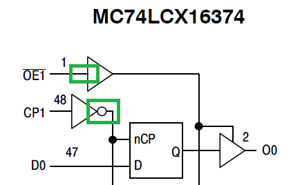
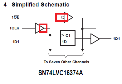
Looks they are P2P but we saw  have some different on LOGIC DIAGRAM.and FUNCTION TABLE.

The LOGIC DIAGRAM different i show as below, the FUNCTION TABLE different are item 3 CLK.

TI is L/H but ON only show low.

So could you help double confirm which datasheet are correct and  it's really can direct replace? Thanks!!

ON

TI

  • The OE1 input requires a low signal to enable the outputs, so it is correct to show the inverter bubble. The ON logic diagram appears to be wrong. (The truth table is correct.)

    The clock input triggers on a low-to-high transition, so the signal must not be inverted. But it's possible that "nCP" means "negated clock pulse".

    The third entry in the truth tables is supposed to show what happens where is not a low-to-high transition, i.e., either low or high or a high-to-low transition.

    In any case, the actual behaviour of both devices is exactly the same.