This thread has been locked.

If you have a related question, please click the "Ask a related question" button in the top right corner. The newly created question will be automatically linked to this question.

SN74LVC2G14: Input Current showes different with the datasheet

Part Number: SN74LVC2G14

Dear Sir:

Recently my encoder needs two channels of Schmitt Trigger Inverter for signal shaping.

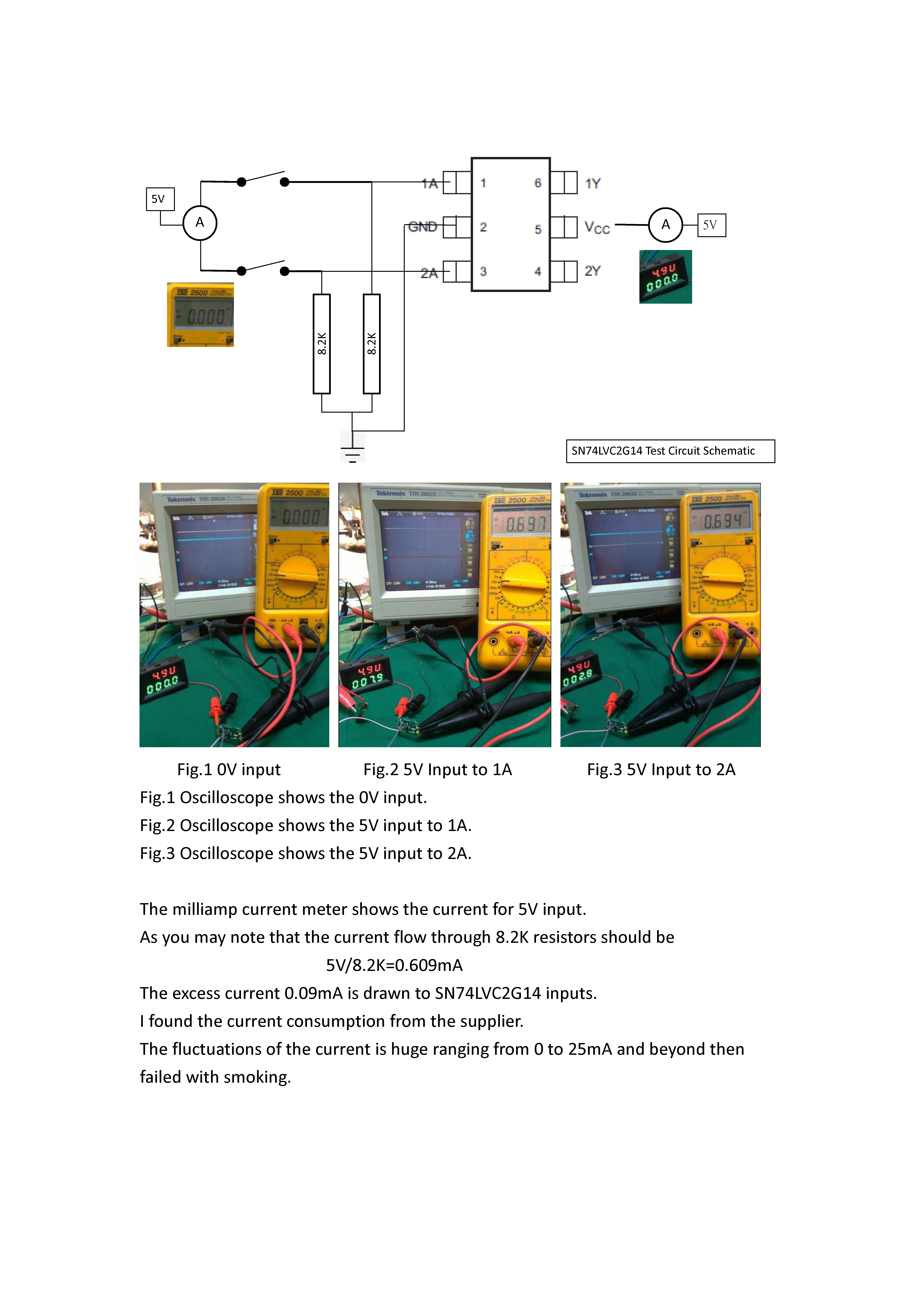
The circuit is shown as

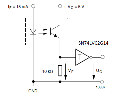
Having done repeatly failing, I finally checked the input current of SN74LVC2G14.

Astonishing me, the current of each channel is different to each and to the datacheet.

The tests were done as only a device of SN74LVC2G14 itself.

1. I powered it with 5V.

2. I hooked the inputs 1A & 2A with 5V or GND and miliamp meters in line.

3. I probed the outputs 1Y & 2Y on oscilloscope.

I find repeatly 1A channel always failed and draw amount of current shown on the meter when hooked to 5V.

The fluctuations are terrible then the device failed that channel.

Please so kind of troubleshooting my problem that I have been wasting so many SN74LVC2G14.

Best Regards

Dr. Alex Chang  


  • Hi Chao,

    The current flowing into or out of the inputs of the inverter should be less than 5uA as per the datasheet.

    How much current are you seeing on the inputs of the inverter?

    Thanks!

    -Karan

  • Dear Karan:

    Sorry for late response.

    In my experiments on the SN74LVC2G14 itself, it drew amount current on 1A channel in fluctuating from 0.5mA to 10mA, then failed.

    Best Regards

    Dr. Alex Chang 

  • A CMOS input should be high impedance. Current flows only when voltages outside the valid range trigger the ESD protection circuit, or when the input has been damaged (probably due to overvoltage).

    Can you check with an oscilloscope if there are spikes in the input voltage? Were the failed devices ever handled without proper ESD protection?

  • Hello Dr. Alex,

    As Clemens has mentioned, confirm that input voltage is at valid voltage levels. Can you also provide scope shots of your input voltages? It sounds like the inputs are getting damaged which is causing this large current leakage on the input either through the ESD diodes or the clamp diodes.

    Thanks!

    -Karan

  • Hi,

    Is your ammeter only in series with one of the inputs? Because otherwise you should have 1.2mA of input currents.

    Have you made sure your whole system is on the same ground? The GND of your supplies is the same as GND on device and resistors. I feel something is floating on the device that is causing this input current to vary so much. Is the supply of your VCC staying at 5V or is it fluctuating?

    Based on your picture, there is a large chance of ESD damage. Are your properly setting up your test to avoid any chance of ESD strikes?

    Thanks!

    -Karan

  • Dear Karan:

    Yes, my ammeter is in serial to the input.

    Yes, the whole system is on the same ground.

    The 5V power supplier is Laboratory class.

    How do you find my diagram is in large ESD damage situation?

    If so, how do I avoid the ESD?

    Best Regards

    Dr. Alex Chang

  • Hello,

    So if input is in series with two input resistors your input current will be 1.2mA correct?

    Are the outputs floating?

    Can you measure voltage across 8.2k resistor to confirm it is 5V? Is input connected to 5V supply?

    I am saying large chance of ESD damage because you are using in open environment where you could damage the device by connecting or disconnecting wires while they are charged. There can also be damaged if you physically touch the part with your hands.

    Thanks!

    -Karan