Other Parts Discussed in Thread: SN74HCS74
Hi,
I am using the part "SN74LVC1G74" in my design. The block diagram is as mentioned below.

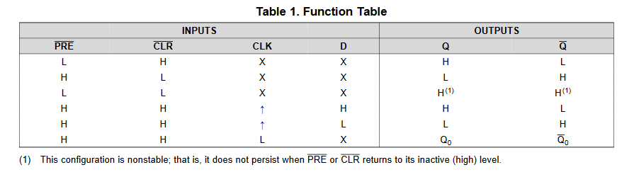
CLR#, PRE# and Q is connected to Processor. Q# is not connected. CLK is connected to timer circuit and Q should go high only if any Rising Edge is found on the Timer output. Data pin is connected to VCC always.
I am doing DO-160 power interrupt test on the system level and have below observation.
‘Q’ output is going high when I do D0160 power interrupt test on system level.
I have 50ms hold up time in system level. When I do the power interrupt test for 20ms, my system should not restart and it continue working as earlier.
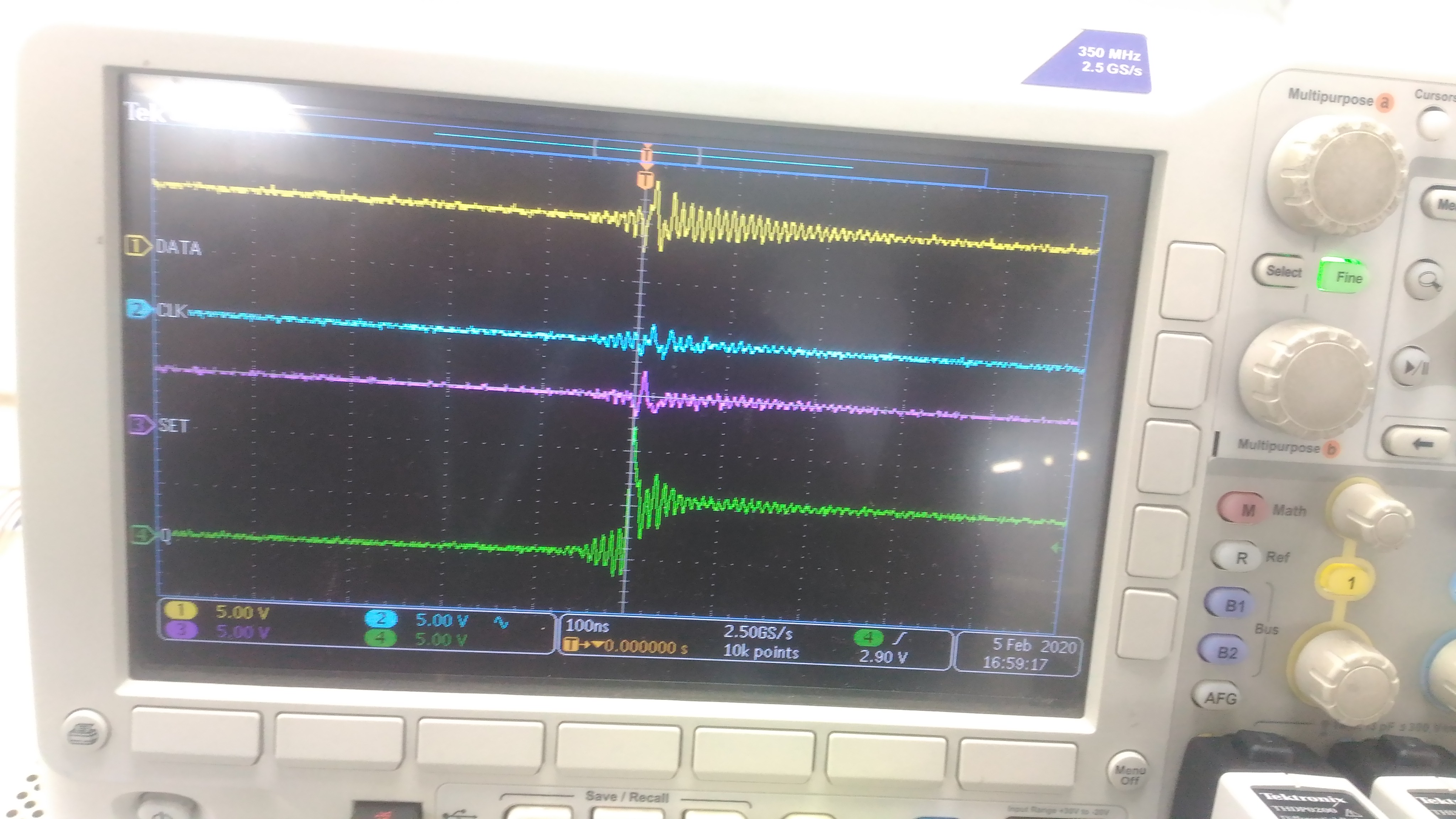
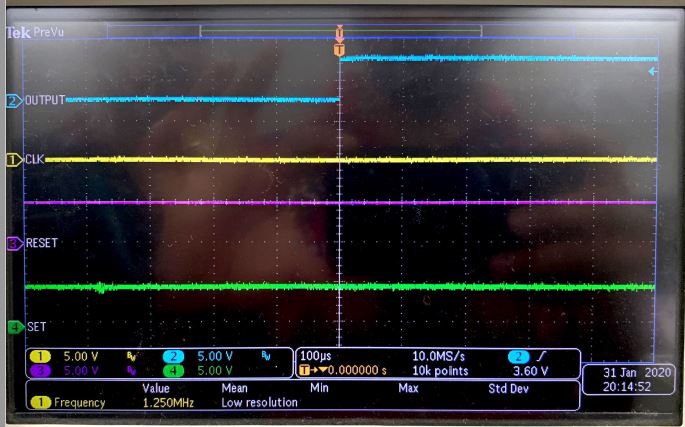
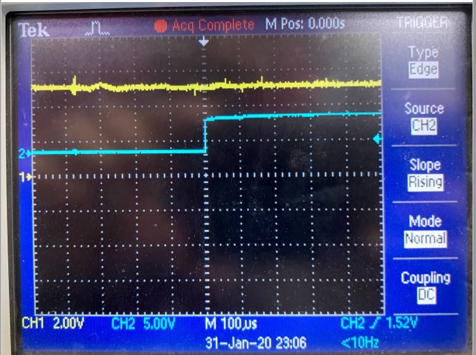
When I do the power interrupt for 20ms, Q is going to High, which is not supposed to. I have probed all the signal during this test and no trigger is observed on any of the signals.
Please guide me to understand the reason for this. Let me know if any additional information is required.
Probing Points are mentioned below.
I am using the part "SN74LVC1G74" in my design. The block diagram is as mentioned below.
CLR#, PRE# and Q is connected to Processor. Q# is not connected. CLK is connected to timer circuit and Q should go high only if any Rising Edge is found on the Timer output. Data pin is connected to VCC always.
I am doing DO160 power interrupt Test on the system level and have below observation.
‘Q’ output is going high when I do D0160 power interrupt test on system level.
I have 50ms hold up time in system level. When I do the power interrupt test for 20ms, my system should not restart and it work as how it was working before 20ms.
When I do the power interrupt for 20ms, Q is going to High, which is not supposed to. I have probed all the signal during this test and no trigger is observed on any of the signals.
Please guide me to understand the reason for this. Let me know if any additional information is required.