This thread has been locked.

If you have a related question, please click the "Ask a related question" button in the top right corner. The newly created question will be automatically linked to this question.

SN74LV74A: Please advise us how to calculate capacitor value.

Part Number: SN74LV74A

Hi,

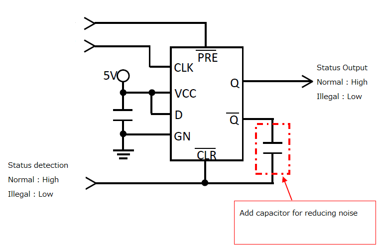
He wants to add capacitor between /Q pin and /CLR pin to reduce noise.

On normal condition, /CLR pin is High and /Q pin is Low. However if status is illegal, both pins are opposite and he has to select capacitor value Not to exceed MAX current (12mA).

Please let him know how to calculate capacitor value.


Thanks and best regards,
M.HATTORI.

  • Hi Motoyasu,

    Is there a specific reason they're adding the capacitor from /Q to /CLR?

    If the customer is simply trying to eliminate noise on the /Q output, I would suggest the capacitor connect /Q to GND instead of to /CLR.

    Thanks!

    Chad Crosby

  • Hi, Crosby-san,

    >>Is there a specific reason they're adding the capacitor from /Q to /CLR?
    >>If the customer is simply trying to eliminate noise on the /Q output, I would suggest the capacitor connect /Q to GND instead of to /CLR.

    He understood it is good that the capacitor is connected with GND.

    After he made the board, he found the issue due to the noise on /CLR line.  But Only /Q pad is available, (NO GND PAD). That is why he is asking.
    Please advise us.

    Thanks and best regards,
    M.HATTORI.
  • Hi Motoyasu,

    Placing a capacitor between \CLR & \Q would only make the problem worse. I would strongly suggest changing the board design to include pads for a capacitor. 

    If this is not possible at all, could you please include a screenshot of the board so I can see if there's a better option.