This thread has been locked.
If you have a related question, please click the "Ask a related question" button in the top right corner. The newly created question will be automatically linked to this question.
Hi team,
My customer uses LSF0102 for 3.3V to 5V UART signal translate, they observed the logic low of the signal of both 3.3V and 5V is pulled up to several hundreds mV, see below scope shot. they have tried remove LSF0102 from board and 3.3V becomes normal. What could be the reason?
These two signals are from A1 and A2.
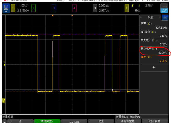
The above is from B1.
Thanks and regards.
George
The LSF is a passive switch with a certain resistance. If you are using small pull-up resistors, the current through and the voltage drop over the switch becomes larger. (And the output voltage of the device that is actually driving the line becomes larger, too.)
Try to use larger pull-up resistors, if this is possible with the desired signal frequency. Alternatively, use a different translator; see [FAQ] Are there voltage level translation / level shifter device recommendations for the industry standard interfaces like GPIO, SPI, UART, I2C, MDIO, RGMII, I2S etc?
Hi George,
Clemens is correct. This is explained in detail in this video: https://training.ti.com/down-translation-lsf-family?context=1134826-1139264-1134793
Hi Clemens,
Thanks for the reply, I have go through the videos and understand your point that there will be voltage drop on the device when it's on.
But in my customer case, data now is going from 3.3V to 5V, so the current goes from 5V side to 3.3V side, the voltage at B should be higher than A, but the result shows otherwise. I think there might be other reason.
Can you help further explain? Thanks!
George
Also in the datasheet it says LSF0102 is also suitable for UART, what is the difference between LSF0102 and TXB0104?
These voltages imply that some other device sinks current. Is there anything else connected to these signal lines?
I do not know why that table mentions four-channel devices for UART. You could use the TXS0102 (which is like the LSF0102, but with edge accelerators, which allows it to use much larger pull-up resistors) or the TXB0102 (which has very weak output drivers and does not work well with pull-up/-downs).
I would have recommend a direction-controlled translator (with proper output buffers) for this, but there is no 5 V device that allows two channels in opposite directions. So for the 3.3 V to 5 V translation, I suggest a buffer with TTL-compatible input (e.g., SN74AHCT1G125), and for the 5 V to 3.3 V translation, a buffer running at 3.3 V with overvoltage-tolerant input (e.g., SN74AHC1G125).