Hi,
I am working in a new design, looking for a bi-directional level translator for GPIOs (1.8V to 3.3V). the GPIOs load setting of 8 Ma (max could be <16mA). and have internal PD (min:35K , typ. 50K, max:65K). Externally, I have and LED on GPIOs and 1K pull up (below diagram). I am not sure if this will cause any issue because statement in specification that "TXB0104 is designed to drive capacities loads of up to 70pF. The output drivers of the TXB0104 have low DC drive strength. If pull-up or pull down resistors are connected externally to the data I/Os, their values must be kept higher than 50 kΩ to ensure that they do not contend with the output drivers of the TXB0104.” If below is causing an issue, any idea how to fix...
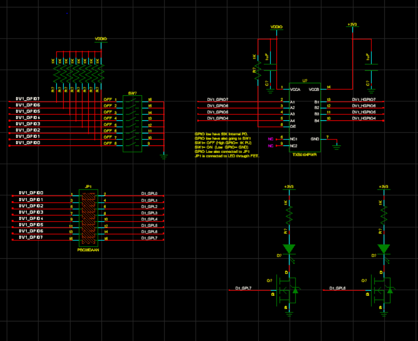
In Summery this is what I have: GPIO low have 50K Internal PD; GPIO low have also going to SW1; SW1= OFF (High GPIO= 1K PU); SW1= ON (Low GPIO= GND); GPIO Low also connected to JP1; and JP1 is connected to LED through FET (Below sch)