This thread has been locked.

If you have a related question, please click the "Ask a related question" button in the top right corner. The newly created question will be automatically linked to this question.

CD74HC4060: CD74HC4060m96

Part Number: CD74HC4060

Schematic of RC or Crystal-Oscillator for CD74HC4060

  • Hi Odair,

    I see that you have a question regarding the use of the CD74HC4060, but it looks like you forgot to include any explanation for what you're looking for. I'm just going to guess that you'd like to see an example schematic for an RC and Crystal Oscillator setup for the CD74HC4060.

    First, let me show the block diagram of the device itself:


    The yellow highlighted portion of the device is the oscillator circuit.  As you can see, there are essentially two inverters in the loop, (one is a NAND gate) and all three connections for these are accessible from outside the device.

    From this, you can build several different versions of an oscillator circuit, or you can feed in an input directly from an external clock. 

    If you already have an external clock that you'd like to use, you can attach it directly to pin 11 and leave pins 9 and 10 floating.

    If you want to create an RC Oscillator circuit, you can replicate this circuit with values of R1, R2, and C1 appropriate for your application:

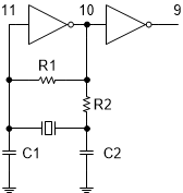
    If you want to create a Crystal Oscillator circuit, you can replicate this circuit with values of C1 & C2 recommended by your crystal datasheet. R1 is typically 1 Mohm, and R2 is typically 2.2kohm.

    If you have additional questions, please let me know.