This thread has been locked.

If you have a related question, please click the "Ask a related question" button in the top right corner. The newly created question will be automatically linked to this question.

LSF0204: Multiple logic levels really possible?

Part Number: LSF0204

Hi,

The documentation for the LSF0204RGYR is not very clear and has several errors and incomplete sentences not to mention conflicting examples. It claims you are able to use each channel to translate different voltages (from A to B or from B to A) but then gives a conflicting example.

Basically I want to use 3 channels to translate I2C at 3.3v to 1.8v AND THEN use the fourth channel to translate a 3.3v signal to 5v.

Question 1) Can this be done?

Question 2) What should VrefA and VrefB be set to?

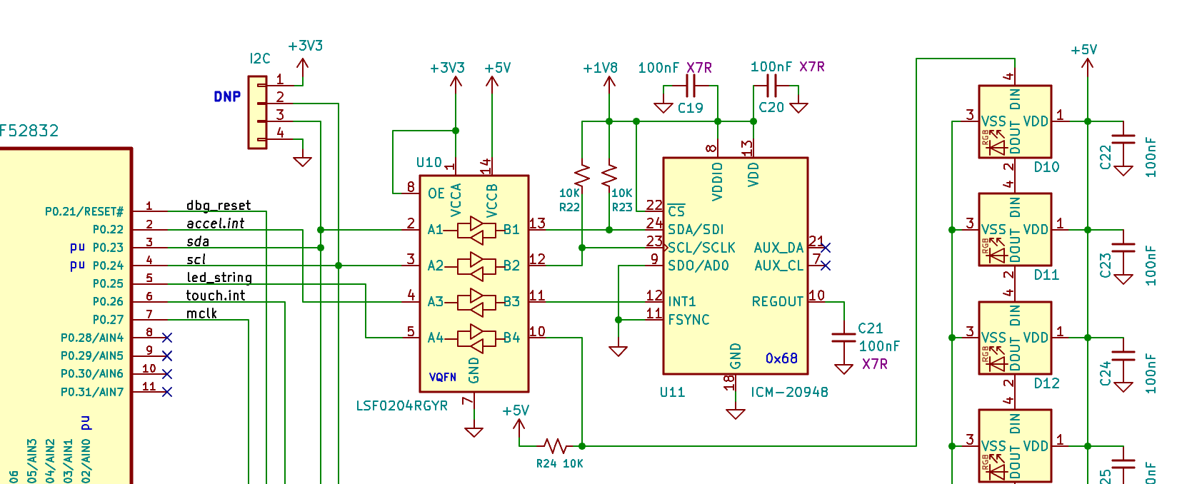
Here's a partial schematic:

Thank you,

Kevin

bard-designs.com

  • Table 3 shows the requirements. Connect Vref_A to 1.8 V and Vref_B to 5 V (or 3.3 V).

    The interrupt signal requires a pull-up resistor on the 3.3 V side.

    Depending on the capacitances on your board, 10 kΩ might be too large for fast signals; check the waveforms with an oscilloscope.

  • Thank you Clemens. What is the purpose of the VRefA and VRefB if pull-ups are used on the A and B sides to keep the signals high (unless the other side is driving them low)?

    You mention connecting VRefB to 3.3v or 5v. Must is not be 5v since pin 10 has a pull-up to 5v?

    And thanks for the heads up on the 10k's. They should work given their very close proximity to the connected parts but I'll double check with a some.

    Much appreciated. Thanks!

  • Vref_A and Vref_B are connected to a circuit that biases the gates of the pass transistors to be the threshold voltage above Vref_A. This allows you to omit the A-side pull-up resistor if you are translating down from B to A and if the load on the A side has a very high impedance. See Voltage-Level Translation With the LSF Family for details.

  • Wonderful. Thank You!