Because of the holidays, TI E2E™ design support forum responses will be delayed from Dec. 25 through Jan. 2. Thank you for your patience.

This thread has been locked.

If you have a related question, please click the "Ask a related question" button in the top right corner. The newly created question will be automatically linked to this question.

TXB0106: TXB0106 application

Part Number: TXB0106
Other Parts Discussed in Thread: SN74AHC541, SN74LVC244A, TXB0104, SN74AXC4T774

Hi Team,

I have some issue by using TXB0106.

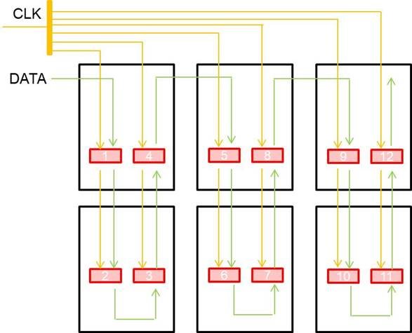
Below is schematic diagram. The red block is TXB0106 for SPI signal/clk translation.

  1. 3.3Vin and 3.3Vout, using for driver
  2. The data rate is 7Mbps
  3. Use external power supply to provide 3.3V
  4. We measured the TXB0106(1) and TXB0106(12) data/clk waveform is match and good.


The issue description is showing as below.

  • When ambient temp is up to 60C, we see the flicker on LED. We consider that the reason is that clk signal was affected. (The data seems ok.)
  • When we measure the clk pin (one of TXB0106 output pin(input is connect to clk)), the flicker is more serious.
  • We also connected a long wire(50cm) to one of TXB0106 output clk pin, the flicker is also more serious, but the LED is stable when we hold the termination of the wire.


Could you let me know the reason for above state based on your experience? 

Regards,

Roy

  • Connecting a TXB output to a TXB input violates the restriction in section 8.3.2 of the datasheet:

    For proper operation, the device driving the data I/Os of the TXB0106 must have drive strength of at least ±2 mA.

    Using long traces, cables, or connectors is likely to violate the restrictions in section 8.3.4:

    TI recommends careful PCB layout practices with short PCB trace lengths to avoid excessive capacitive loading and to ensure that proper O.S. triggering takes place. PCB signal trace-lengths should be kept short enough such that the round trip delay of any reflection is less than the one-shot duration. This improves signal integrity by ensuring that any reflection sees a low impedance at the driver. The O.S. circuits have been designed to stay on for approximately 10 ns. The maximum capacitance of the lumped load that can be driven also depends directly on the one-shot duration. With very heavy capacitive loads, the one-shot can time-out before the signal is driven fully to the positive rail. The O.S. duration has been set to best optimize trade-offs between dynamic ICC, load driving capability, and maximum bit-rate considerations. Both PCB trace length and connectors add to the capacitance that the TXB0106 output sees, so it is recommended that this lumped-load capacitance be considered to avoid O.S. retriggering, bus contention, output signal oscillations, or other adverse system-level affects.

    To properly buffer the signals, use an actual buffer like the SN74LVC244A or SN74AHC541.

  • Hi Ladisch,

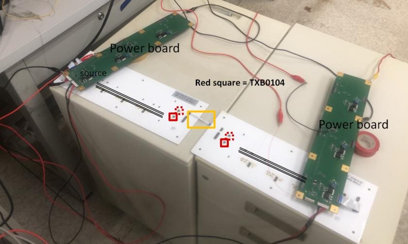
    Thank you for your comments. We narrow down the range of issue, but we need your suggestion based on your experience. Below is our setup, the red solid/dotted line are all TXB0104.(1clk/3data) And now only solid square is working.


    Below is the condition :

    1. Only use one light board(means white board) : There is no flicker. Even in high ambient temp.
    2. Use two light board(Connected by orange wire) : There is flicker when ambient temp is higher than 50C. The flicker is more serious when ambient temp is higher.


    We think the 2nd board has impact to 1st board due to noise coupling. But we have no idea how to avoid the noise. And why high ambient temp cause the more serious flicker. Do you have any idea for this issue?

    Regards,

    Roy

  • As I already wrote, the TXB cannot cope with the capacitance of the connection between the boards. It is not possible to keep using the TXB.

  • Hi Ladisch,

    Yes, I have suggest customer use dir-controlled part as buffer in next gen.(sn74axc4t774)

    But we still would like to know that why high ambient temp cause the issue. If we transfer the high drive current part could fix the issue?

    Actually, only one board worked, the signal is stable, but they use two TXB0104 to tranfer signal.You could see the solid red line in first white board. So I think the TXB0104 isnt a only factor cause the flicker.

    Do you have any suggestion?

    Regards,

    Roy

  • The cable can introduce ringing, which will make the TXB outputs oscillate.