This thread has been locked.

If you have a related question, please click the "Ask a related question" button in the top right corner. The newly created question will be automatically linked to this question.

TXB0108: Oscillation at output

Part Number: TXB0108

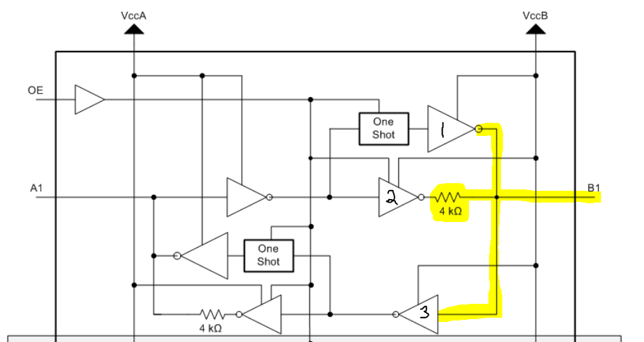
I have used the TXB0108 IC to translate voltage between 3.3V(VccA) and 5V(VccB).

 When i provide a high logic level at any of the 3.3V channels the corresponding output channel does not reach 5V and starts oscillating at a frequency >40 Mhz. ( tested using an oscillioscpe to test with 1Mohm resistance and 13pF capacitance at input).

When i tried connecting a series resistor of ~1k to the output channel, the oscillations seem to dissappear and 5V output is seen, but for a low level input (0V), the ouput seems to be around 1.6V.   

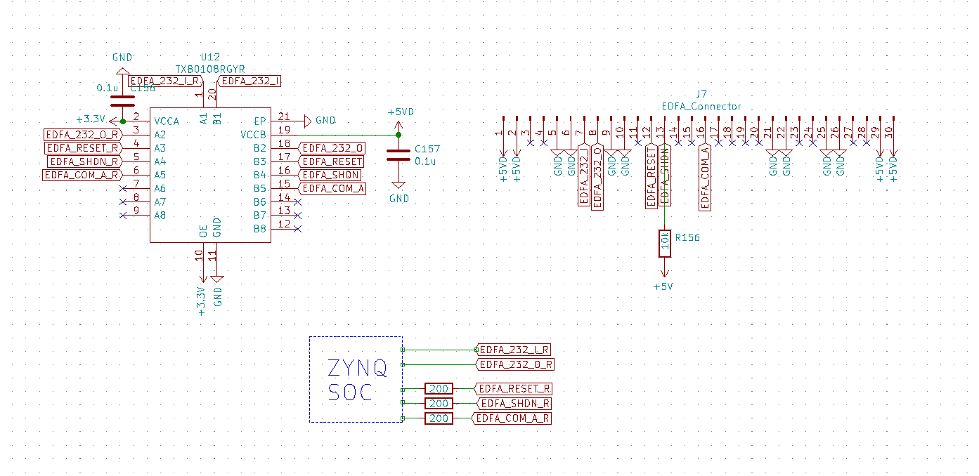
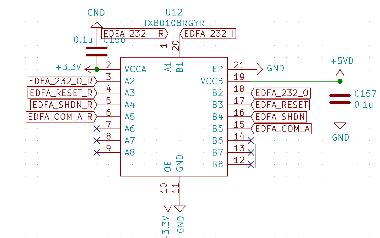
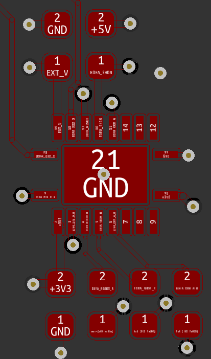
I am attaching the schematic and Layout here.

I have used 200 ohm series resistor with the input channels. 

Also attaching the output of one of the channels (without any resistors in series at the output

I have used 5 out of the 8 channels and left the remaining channels unconnected. OE pin is directly interfaced with 3.3V since I'm not using the pin.

So far, the mistakes i did was that i left the unconnected channels open, it should have been grounded instead. And I had used a pull up resistor (10k) in one of the output. 

I am facing the oscillation issue in all the channels, what could be the issue?

  • Oscillations happen with TXB/TXS translators when there is ringing on the signal lines; this can cause the edge accelerators to falsely trigger. Typically, you get ringing from a high capacitive/inductive load, i.e., long traces, connectors, or cables.

    How many signals in each direction do you have? Is any single signal actually bidirectional?

  • Hey Clemens, thanks for the quick reply.

    The traces on the board are around 50mm in length. Is it a cause for concern?

    Two of the signals are birectional (UART signals) others are unidirectional signals, ( although so far, i have only checked all the signals in one direction, i.e from 3.3V->5V)

    I will trying reading the signals at the input of TXB and confirm if there is any ringing.

  • When the UART signals are bidirectional, why are they labelled as "I" and "O"? Is there any single signal that can go in different directions at different times?

  • Hey Clemens,

    Sorry, my bad, I got confused a bit with the UART. Yeah, All the signals are unidirectional. There is no single signal that is bi-directional. All are unidirectional.

    RInging should occur only at high speeds right, the oscilloscope output i have provided is for a 1 Hz signal. Anyways, I'll get back with the input waveform.

  • Ringing at the signal edges at any ouput is a problem.

    Anyway, level shifting of unidirectional signals works better with buffering; use any LVC translator. But for 5 V to 3.3 V downshifting, you could simply use any buffer with overvoltage-tolerant inputs, and for 3.3 V to 5 V, you could use any buffer with TTL-compatible inputs.

  • Hey Clemens,

    Thanks a lot for your input, I really appreciate it. But if i am changing the components, that would mean a change in the PCB board also. I wanted to avoid that.

    This is the rising edge of a 100 Khz signal at one of the inputs, as you can see there is not much ringing and does not seem to fall below the VIH threshold value to trigger any false outputs.

    If nothing else works, i will have no option than to change board design and use the components that you have suggested. (As i could not find any pin to pin compatible Ic's in the ones which you have suggested).

    Anyways, Thanks a lot.

  • Hello,

    The TXB translator has this architecture:

    I highlighted everything connected directly to the B1 pin for clarity.

    You can see that there are two outputs connected together labelled 1 and 2 above. Output 2 is always active, while output 1 only activates when a change is detected at the A1 input.

    For any auto-bidirectional voltage translators, you shouldn't be using any series resistors.

    Your schematic only shows the TXB0108 -- can you also show the resistors and anything else connected to input and output which are having the issue?

  • Hey Emrys Maier, 

    Thanks for the reply.I have attached a simplified end-to-end schematic here.

    As you can see, two of the channels (they are used for UART, does not have any series resistor or pull-up/down resitors used with them), still i am able to find the oscillation in those pins too.

    I'm not able to discern the nature of the oscillation properly, since the oscilloscope I'm using is a 50 Mhz one.

    It could be as clemens mentioned due to ringing at input and the one shot getting triggered continuously, but i was unable to find any such ringing at input.

  • The ringing is not at the input but at the output. Because of the bidirectional I/Os, it can be interpreted as a signal edge going in the opposite direction.

    And there is indeed a connector. This board violates the restrictions in section 8.3.3 of the datasheet. As a rule of thumb, TXB translators can be used only between nearby chips on the same board.

  • Hey Clemens,

    That makes a lot of sense, and is most probably the issue. Thanks for your inputs.