This thread has been locked.

If you have a related question, please click the "Ask a related question" button in the top right corner. The newly created question will be automatically linked to this question.

LSF0108: Vrefb> Vrefa+0.8v? What's the reason?

Part Number: LSF0108
Other Parts Discussed in Thread: LSF0102

Hi team,

My customer is using the LSF0108 now. As you know the device can support 1.2v to 1.8v voltage change. My customer uses the device to achieve 1.05v to 1.8v change. Whether we need to keep the Vref_B higher than 1.85v? What's the reason of +0.8v? Thanks.

  • The voltage difference must reach the threshold voltage of the pass transistors. See [FAQ] How do the LSF translators work?

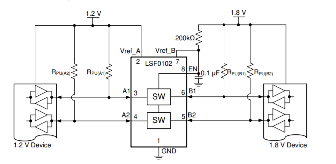
    Please note that it is possible to connect the resistor at Vref_B/EN to any higher voltage while keeping the data pull-up resistors to 1.8 V.

  • Hi Clemens,

    Thanks for your support.  Could you please share more about the connect the resistor at Vref_B/EN to any higher voltage while keeping the data pull-up resistors to 1.8 V.

    How to do the setup if we want to do 1.05v to 1.8v  voltage change? Could you please help share the reference design? Thanks.

  • If you have any other voltage in the circuit (2.5 V or 3.3 V or 5 V), simply connect the 200 kΩ resistor to there.

  • Hi Clemens,

    Thanks. So why the device can support 1.2v->1.8v as below? From excel, the Vref_B/EN should be  0.8v larger  than Vref A. Thanks.

  • Hi Frank,

    In the case given above, the bias voltage on the LSF0102 is too low and will result in the channel clamp voltage decreasing to ~1V (1.8V - 0.8V). Since there are pull-up resistors on both sides of the LSF0102, then the circuit will continue to function normally.

    In reality, the device doesn't have a fixed threshold voltage. The threshold voltage changes slightly due to multiple variables, and it can have values between 0.5V and 0.8V.  We recommend to keep a minimum of 1V difference between the supplies to allow ample room for the bias circuit to operate and produce the correct clamp voltage for this channel. This is particularly useful in the case of down-translation. For example, if you want to down-translate from 5V to 1.8V, then there is no need for pull-up resistors on the 1.8V side of the device as long as the bias circuit is correct.

    This all explained in detail in this video series: Understanding the LSF family of bidirectional, multi-voltage level translators

  • Hi Emrys,

    Do you mean it's because the A, B side signal has pull up resistors, so we need to keep the 0.8v or 1v voltage gap? If we don't use the signal pull up  resistors, we need to make Vref b> Vref a+1v, correct? Thanks,

    Emrys Maier said:

    Hi Frank,

    In the case given above, the bias voltage on the LSF0102 is too low and will result in the channel clamp voltage decreasing to ~1V (1.8V - 0.8V). Since there are pull-up resistors on both sides of the LSF0102, then the circuit will continue to function normally.

    In reality, the device doesn't have a fixed threshold voltage. The threshold voltage changes slightly due to multiple variables, and it can have values between 0.5V and 0.8V.  We recommend to keep a minimum of 1V difference between the supplies to allow ample room for the bias circuit to operate and produce the correct clamp voltage for this channel. This is particularly useful in the case of down-translation. For example, if you want to down-translate from 5V to 1.8V, then there is no need for pull-up resistors on the 1.8V side of the device as long as the bias circuit is correct.

    This all explained in detail in this video series: Understanding the LSF family of bidirectional, multi-voltage level translators

  • No, quite the opposite.

    Because you have pull-up resistors, the incorrect bias won't cause any problems.  If you were to remove the pull-up resistors, then you would see incorrect outputs.