This thread has been locked.

If you have a related question, please click the "Ask a related question" button in the top right corner. The newly created question will be automatically linked to this question.

TXB0104: Output in middle level issue

Part Number: TXB0104
Other Parts Discussed in Thread: DRV8834, SN74LV4T125, SN74AXC4T245

Hi Team,

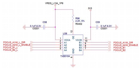
Below is my customer's circuit of TXB0104 for 1.8V to 3.3V signal level shift. A port is connected to MCU(control side) directly without any R, C in series. B port is connected to DRV8834(slave side).

There is only one channel has issue that the output level is only 1.1V in B port when MCU drive 1.8V signal to A port. The output pin is connected to DRV8834's nSLEEP pin that has 500Kohm pull low resistor internally. I ordered TXB0104 samples and do the same test, then I can replicate this issue.

When I tried to connect TXB0104's VCCA and OE pins together and pull up to 1.8V through 2.2K resistor, this issue is solved. One pin in B port with a 500K ohm pull down resistor can output correct signal level, almost at 0V or 3.3V.

My customer will do the same test to check if it works at his real board but he would like to know the root cause. Besides, any side effect if VCCA is connected  to 1.8V vis a 2.2K resistor?

Thanks very much.

Vincent Chen

  • In theory, 500 kΩ should not be a problem for a TXB output driver. Is it possible that one of the A signals is too weak; what are the voltages at the A pins?

    But this application does not need a bidirectional shifter. Better use a shifter with proper buffers, e.g., SN74LV4T125 or SN74AXC4T245.

  • Hey Vincent,

    Based on the data there is nothing really to cause that output not to drive Vcc unless there is some heavy loading or a stronger pull-down. I wouldn't recommend connect the supply pin to the supply through a resistor.

  • Hi Clemens, Dylan,

    Thanks for the comments.

    A signal is from SOC and its voltage is 1.8V, I can check with customer the SOC's GPIO driving capability. 

    In customer's application, the rest 3 pins are connected to DRV8834's input pins which don't have pull low resistor. The function of these 3 pins are all work well.

    As I mentioned that I got samples and do the same test, connecting VCCA to 1.8V, VCCB to 3.3V, OE pin to 1.8V through a 2.2K resistor, B1 pin to a 500K ohm pull down resistor to ground, let rest pins floating. Then, I connect A1 to ground and B1 output 0V, connect A1 to 1.8V and B1 only output 2.0V(in customer's real board the output is 1.1V). 500Kohm is not a heavy load but why B1 cannot output a normal signal?

    If VCCA pull up to 1.8V with a pull up resistor is not recommended, is any method to solve customer's issue? Please let me know if any experiments we can do to to figure out his issue.

    Thanks a lot.

    Vincent Chen

  • Can you measure any currents into or out of A1/B?

  • Hi Clemens,

    Since it doesn't happen every time, when output half level happen, the sink and source current is about 10mA at A1. B1 output current is about 4mA with a external 500Kohm pull down resistor.

    If output signal is normal, the sink/source current is pretty small that I cannnot measure it. It should be under uA level.

    Thank you.

    Vincent Chen

  • Sorry for a typo.

    B1 output current is about 4uA with a external 500Kohm pull down resistor.

  • Hey Vincent,

    Is it safe to assume you also meant 10 uA? 4 uA over the 4kohm series resistor would not cause the drop you are seeing. Do you still see this low voltage with no pull-down?

  • Hi Dylan,

    1. When output pin is clamped at half level, the A port(input port) sink 10mA.(it is hard to measure, mostly I used current meter to probe the sink current then output pin(B port) drop to 0V and sink current at A port is almost 0mA. I tried a lot of times to get this result)

    2. Without 500K pull down resistor at B port, when output half level happen then I measure the output port's sink current. It is about 0.8mA.

    Without 500K pull down resistor, I switch input pin between 1.8V and ground then sometime half level issue appear.

    Thanks a lot.

    Vincent Chen

  • Hey Vincent,

    Does this issue appear when the B port is isolated (not connected to anything)?

    Edit: Can you also zoom in on one of the half levels to get better resolution on what's happening.

  • Hi Dylan,

    Yes, I didn't pull any pull up/down resistor on B port but oscillator's probe.

    I captured the abnormal waveform again with full bandwidth, it oscillates at half level.

    Zoom in the waveform.

    Thanks a lot.

    Vincent Chen

  • Hi Dylan,

    I solder a wire on input pin(A port) and let it to touch 1.8V directly then touch ground via 300ohm series to do the test. I think it is not a proper way to have a 300ohm series resistor. I removed it and do the test again, the wire touches 1.8V or ground directly. It is very hard to replicate this phenomenon but I still can find half level waveform appear. I am not sure it is caused by bouncing or not. I did it on A1 and A2, and I can replicate.

    When I put 500K pull low resistor on B port, it became easier to replicate this abnormat issue.

    Thanks a lot.

    Vincent Chen

  • Hey Vincent,

    What are the transition rates? Are you meeting the transition rate requirements listed in section 6.3? Slow edges can cause this oscillation issue.